Flat-end vertical milling cutter

A technology of flat end mills and tool holders, which is applied in the direction of milling cutters, milling machine equipment, manufacturing tools, etc. It can solve the problems that the tools are not suitable for processing grooves, can not exert the left-handed edge to suppress burrs and delamination, and achieve the elimination of delamination and burrs, and the effect of improving surface finish quality

Active Publication Date: 2016-03-02
ZHUZHOU CEMENTED CARBIDE CUTTING TOOLS CO LTD
View PDF8 Cites 14 Cited by
  • Summary
  • Abstract
  • Description
  • Claims
  • Application Information

AI Technical Summary

Problems solved by technology

However, there are two deficiencies in this milling cutter: one is that the tool must be used in cutting conditions where the axial depth of cut is greater than the axial length of the right-handed edge, otherwise it cannot play the role of the left-handed edge in suppressing burrs and delamination; The second is that the right-handed edge of this kind of tool is usually very short, while the left-handed edge is very long, and the chips are basically discharged downward during processing, so there are certain requirements for the fixture, and the tool is not suitable for machining grooves

Method used


Image

  • Flat-end vertical milling cutter
  • Flat-end vertical milling cutter
  • Flat-end vertical milling cutter

Examples


Embodiment Construction

[0023] The present invention will be further described in detail below in conjunction with the accompanying drawings and specific embodiments.

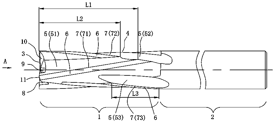
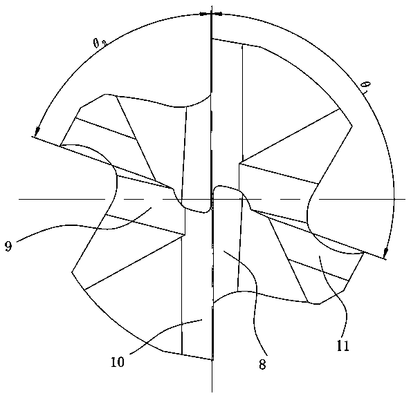
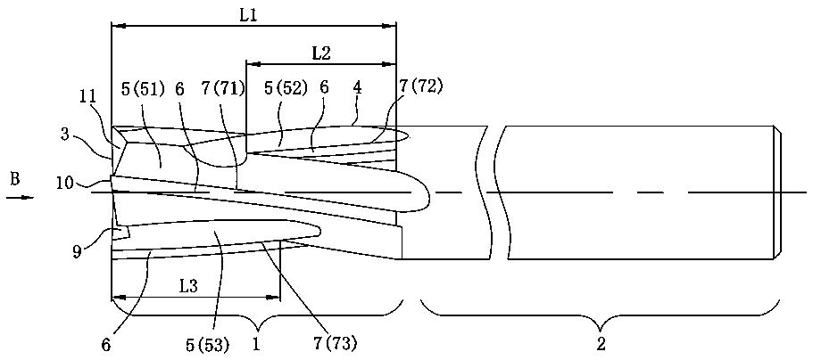
[0024] figure 1 with figure 2 Shown is a first embodiment of a flat end mill according to the invention comprising a coaxial cutting part 1 and a rotary shank 2, the cutting part 1 comprising an end part 3 and a peripheral part 4 on which There are N groups of evenly distributed spiral chip flutes 5, N≥2, in this embodiment, N is equal to 2, and the spiral chip flutes 5 include the first spiral chip flutes extending spirally from the end 3 to the rotary handle 2 51. The second helical chip flute 52 that intersects with the first helical chip flute 51 and rotates in the opposite direction and the independent third helical chip flute 53. The third helical chip flute 53 starts from the first helical chip flute 51 Before the intersection with the second spiral chip flute 52, it ends at the rotary tool handle 2, and the outer peripheral...


PUM


Abstract

The invention discloses a flat-end vertical milling cutter. N sets of evenly-distributed spiral chip grooves are formed in the periphery of the flat-end vertical milling cutter, wherein N is equal to or larger than two. The spiral chip grooves include the first spiral chip groove, the second spiral chip groove and the third spiral chip groove, wherein the first spiral chip groove spirally extends from the end to a rotary cutter handle; the second spiral chip groove intersects with the first spiral chip groove, and the turning direction of the second spiral groove is opposite to that of the first spiral chip groove; the third spiral chip groove is independent. The third spiral chip groove starts from the end and ends in the position behind the intersection of the first spiral chip groove and the second spiral chip groove or starts from the position in front of the intersection of the first spiral chip groove and the second spiral chip groove and ends in the position of the rotary cutter handle. The first spiral chip groove intersects with a rear cutter surface, so that a first cutting edge is formed. The second spiral chip groove intersects with the rear cutter surface, so that a second cutting edge is formed. The third spiral chip groove intersects with the rear cutter surface, so that a third cutting edge is formed. The turning direction of the third cutting edge is opposite to that of the first cutting edge, and the turning direction of the third cutting edge is the same as that of the second cutting edge. The flat-end vertical milling cutter has the advantage that the surface machining quality of a composite material can be effectively improved.

Description

technical field [0001] The invention relates to the field of composite material cutting, in particular to a flat end mill. Background technique [0002] With the development of modern manufacturing industry, composite materials are more and more widely used in modern industry. CFRP and GFRP are the two most widely used fiber composite materials in composite materials. Due to the particularity of the manufacturing process, the mechanical properties of these materials The performance is anisotropic, and the interlayer strength is low. In the process of cutting this kind of material, it is easy to produce defects such as delamination and tearing under the action of cutting force, which reduces the strength and other properties of the component. On the other hand, composite materials such as carbon and glass fiber form chips in the form of brittle fracture during processing. The contact time between the rake face of the tool and the surface to be processed is very short. In addi...

Claims


Application Information

Patent Timeline
IPC IPC(8): B23C5/10
CPCB23C5/1018B23C2210/202
Inventor 曾滔李蓉邓小野李屏
Owner ZHUZHOU CEMENTED CARBIDE CUTTING TOOLS CO LTD
Why Eureka
Try Eureka