
Electromagnetic nozzle based on MEMS process

An electromagnetic force and nozzle technology, applied in piezoelectric/electrostrictive/magnetostrictive devices, piezoelectric effect/electrostrictive or magnetostrictive motors, TVs, etc., can solve the directionality and volume of ink particles Difficult to grasp, uneven edges of printing lines, loud noise of piezoelectric jetting, etc., to achieve the effect of benefiting circuit design, no driving mechanism, and high jetting accuracy

Active Publication Date: 2016-03-02
SHANGHAI UNIV
View PDF7 Cites 2 Cited by
  • Summary
  • Abstract
  • Description
  • Claims
  • Application Information

AI Technical Summary

Problems solved by technology

[0006] Thermal bubble print head is prone to chemical changes at high temperature and its properties are unstable, so the color authenticity will be affected to a certain extent; ink is ejected through air bubbles, and the directionality and size of ink particles are not easy to grasp , the edge of the printing line is easy to be uneven, which affects the printing quality to a certain extent
The micro piezoelectric print head is damaged or blocked, and the whole printer needs to be repaired; under high-frequency jetting, the piezo jet will make a lot of noise

Method used


Image

  • Electromagnetic nozzle based on MEMS process
  • Electromagnetic nozzle based on MEMS process
  • Electromagnetic nozzle based on MEMS process

Examples


Embodiment Construction

[0034] The present invention will be further described in detail below in conjunction with specific embodiments and accompanying drawings.

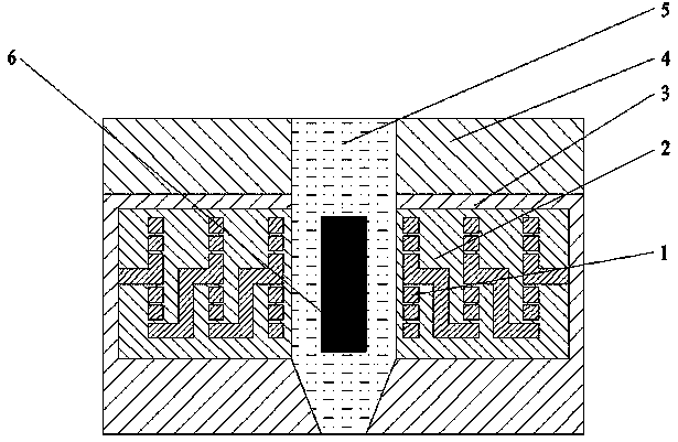
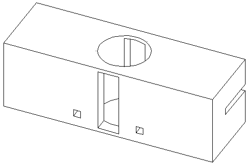
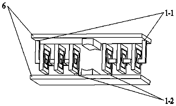
[0035] Depend on Figure 1 to Figure 4 As shown, an electromagnetic force shower head based on MEMS technology includes a conductive coil 1, a soft magnetic material 2, a silicon material 3, a control chip 4, a conductive fluid 5, and an electrode pair 6; the conductive coil 1 is placed on the soft magnetic material 2 Inside, the silicon material 3 is covered with a soft magnetic material 2, the positive and negative poles of the conductive coil 1 are respectively connected to the positive and negative poles of the electrode pair 6, the control chip 4 is placed on top of the silicon material 3, and the conductive The fluid 5 flows out from the bottom of the nozzle hole that runs through the control chip 4, the silicon material 3, and the soft magnetic material 2, and the electrode pair 6 penetrates the soft magnetic material 2, and the si...


PUM


Abstract

The invention relates to an electromagnetic nozzle based on an MEMS process. The electromagnetic nozzle based on the MEMS process comprises a conducting coil, a soft magnetic material, a silicon material, a control chip, a conducting fluid and an electrode pair, wherein the conducting coil is arranged in the soft magnetic material, the silicon material coats the soft magnetic material, the positive electrode and the negative electrode of the conducting coil are respectively connected with the positive electrode and the negative electrode of the electrode pair, the control chip is arranged at the top of the silicon material, the conducting fluid flows out of the bottom of a spray hole penetrating through the control chip, the silicon material and the soft magnetic material, and the electrode pair is connected with the control chip at the top after penetrating through the soft magnetic material and the silicon material, thereby achieving micro-flowing control on the conducting fluid. After the micro electromagnetic nozzle manufactured based on the MEMS process is electrified, the conducting coil in series connection generates a magnetic field, the electrode pair generates an electric field, and an electromagnetic force formed by an electromagnetic field drives the conducting fluid in the nozzle to vertically flow downwards; the electromagnetic nozzle based on the MEMS process has the characteristics of simple structure, high precision and frequency, low noise, low heat and high reliability.

Description

technical field [0001] The invention relates to an electromagnetic spray head based on MEMS technology, which has no noise, no heat, no vibration and no driving mechanism, and is applied in the field of micro-flow control of conductive fluid with high precision, high frequency and high reliability. Background technique [0002] The MEMS manufacturing process is a general term for microstructure processing processes down to the nanometer scale and up to the millimeter scale. Mainly include: integrated circuit process technology (processing silicon materials with thin film deposition, patterning and etching technologies to form silicon-based MEMS devices), LIGA technology (photolithography, electroforming and plastic casting to form deep microstructures to manufacture MEMS device). The main feature of silicon MEMS processing technology is that the deep etching of silicon substrate materials can obtain movable microstructures with large longitudinal dimensions. Silicon process...

Claims


Application Information

Patent Timeline
Patent Type & Authority Applications(China)
IPC IPC(8): B81B7/00B81B7/02B41J2/14
CPCB41J2/14B81B7/0009B81B7/02
Inventor 张金松许阁周志鹏刘超伊春明王志亮
Owner SHANGHAI UNIV
Learn More