Sludge drying and incinerating process

A sludge drying and process technology, applied in incinerators, combustion methods, combustion types, etc., can solve the problems of poor treatment effect and high energy consumption, and achieve the effects of improving efficiency, reducing energy consumption and increasing thermal energy.

Inactive Publication Date: 2016-03-02
江苏碧诺环保科技有限公司
View PDF7 Cites 8 Cited by
  • Summary
  • Abstract
  • Description
  • Claims
  • Application Information

AI Technical Summary

Problems solved by technology

[0004] Therefore, the technical problem to be solved by the present invention is to overcome the problems of high energy consumption and poor treatment effect of the sludge drying and incineration process in the prior art, thereby providing a sludge drying and incineration process with low energy consumption and good treatment effect craft

Method used


Image

  • Sludge drying and incinerating process
  • Sludge drying and incinerating process
  • Sludge drying and incinerating process

Examples


Embodiment 1

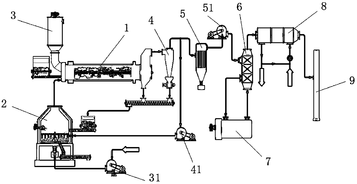
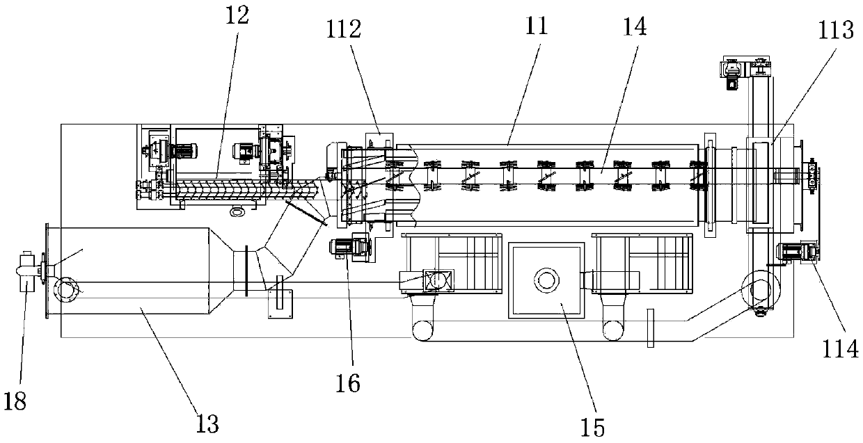
[0046] This embodiment provides a sludge drying and incineration process, such as figure 1 mentioned, including

[0047] Drying equipment 1, used for drying materials, has a gas inlet and a gas outlet;

[0048] A hot blast generator 3 communicates with the gas inlet for feeding hot blast into the drying equipment 1;

[0049] The incineration equipment 2 is used to receive the materials dried by the drying equipment 1;

[0050] The incineration equipment 2, such as Figure 5 or 6, including

[0051] The incinerator 22 has a feed inlet 221 and a high-temperature gas tuyere 225 on the side wall, an air outlet 223 on the top, and a discharge outlet 222 on the bottom;

[0052] The burner 25 communicates with the high-temperature gas tuyere 225 and is used for blowing high-temperature gas into the interior of the incinerator 22;

[0053] Incineration stirring device 21, such as Figure 7 or 8, for stirring the materials in the incinerator 22;

[0054] The incineration stirrin...

Embodiment 2

[0117] This embodiment provides a sludge drying and incineration process, using the sludge drying and incineration process described in Example 1, including

[0118] Put the sludge into the drying furnace and pass it into the drying furnace at 280-350°C, and dry the hot air to form dry sludge;

[0119] Put the dried sludge into the incinerator and pass it into the incinerator at 800-1100°C, such as 800°C, 900°C, 1100°C, etc., for incineration with high-temperature gas;

[0120]Part of the gas discharged from the drying furnace is passed into the incinerator, part of the gas is discharged into the air, and part of the gas is used to generate the hot gas;

[0121] The gas produced by the incinerator is passed into the drying furnace.

[0122] The hot blast generator 3 is used to generate hot gas, and the high-temperature gas in the incinerator is formed by directly blowing into the furnace through the burner.

[0123] The gas discharged from the drying furnace has three destin...


PUM


Abstract

The invention provides a sludge drying and incinerating process. According to the sludge drying and incinerating process, gas exhausted from a drying furnace is led into a hot air generating furnace and an incinerating furnace, so that the gas with a certain humidity is led into the hot air generating furnace and the incinerating furnace; the specific heat capacity of hot gas and high-temperature gas is improved, the thermal energy carried by the hot gas and the high-temperature gas is increased, and the thermal efficiency is improved. In addition, the gas exhausted from the drying furnace is burnt again in the hot air generating furnace and the incinerating furnace so that the thermal energy of retorting gas can be fully utilized, and smelly gas can be removed; the gas generated in the incinerating furnace can also enable the gas generated in the incinerating furnace to be led into the drying furnace to be burned when being led into the drying furnace, and the thermal energy carried by the gas exhausted from the incinerating furnace can be fully utilized. Through the mode, energy consumption in the whole drying and incinerating process is greatly lowered, and meanwhile the efficiency of drying and incinerating is improved.

Description

technical field [0001] The invention relates to the technical field of pollutant treatment equipment, in particular to a sludge drying and incineration process. Background technique [0002] At present, domestic and foreign sludge treatment and disposal methods mainly include landfill, incineration, and land utilization. Sludge landfills occupy a large amount of land, and the leachate and gas produced will seriously pollute groundwater and the atmosphere. When land is used, because the sludge contains pathogenic bacteria, parasite eggs, heavy metals and various refractory organic compounds, it will endanger human health and the growth of animals and plants. Incineration is the most thorough means to realize the harmlessness, reduction and stabilization of sludge, and its proportion in sludge treatment and disposal is increasing year by year. It has become the main technology adopted by developed countries, but its technology and equipment investment is large. The operating...

Claims


Application Information

Patent Timeline
Patent Type & Authority Applications(China)
IPC IPC(8): F23G7/00F23G5/04
CPCF23G7/001F23G5/04
Inventor 蒋子厚蒋子才赵钱亮
Owner 江苏碧诺环保科技有限公司
Why Eureka
Try Eureka