Vacuum furnace for continuous production

A vacuum furnace and vacuum technology, used in furnaces, muffle furnaces, cooking furnaces, etc., can solve the problems of affecting reaction temperature and pressure, long production cycle, troublesome operation, etc., to improve energy efficiency, low processing accuracy requirements, and cost. low effect

Inactive Publication Date: 2016-03-02
JISHOU UNIVERSITY
View PDF6 Cites 1 Cited by
  • Summary
  • Abstract
  • Description
  • Claims
  • Application Information

AI Technical Summary

Problems solved by technology

[0002] Vacuum furnace is one of the equipment often used in metallurgy and new material research and development and production. The existing vacuum equipment generally puts the sample in a fixed crucible first, then vacuumizes and heats it. After reaching a certain temperature, keep the temperature for a certain period of time. Then turn off the power to cool down, and finally take out the product, slag or sample to complete a production, that is, one production needs to include multiple processes of temperature rise, constant temperature and temperature drop, so the production cycle is long, energy consumption is high, and energy efficiency is low.
[0003] On the other hand, the vacuum furnace is a pressure or vacuum operation during the production process, so opening or closing the logistics channel requires breaking the vacuum, which not only affects the reaction temperature and pressure, but also is very troublesome to operate

Method used


Image

  • Vacuum furnace for continuous production

Examples


Embodiment Construction

[0024] Now in conjunction with accompanying drawing, the present invention is described in further detail.

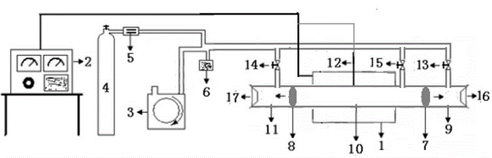
[0025] Such as figure 1 The vacuum furnace for continuous production shown is composed of a vacuum furnace body 1, a temperature controller 2, vacuum acquisition and detection instruments (3 and 6) and an air charging system. The material passage in the vacuum furnace body 1 includes a feed area 9, a product outlet Zone 11 and reaction zone 10, with good sealing and no magnetism, are generally quartz tubes, high-purity corundum tubes or non-magnetic stainless steel tubes; iron baffles 7 and 8 with sealing rings at both ends of the reaction zone 10 can act on the magnetic force of the magnet Open or close the channel, and have good sealing; thermocouple 12 is installed in the middle of the vacuum furnace body, and the bottom is close to the reactor, so as to accurately measure and control the reaction temperature.

[0026] The gas charging system is composed of a gas st...


PUM


Abstract

The invention discloses a vacuum furnace for continuous production. The vacuum furnace comprises a vacuum furnace body, a temperature controller, a vacuum acquisition and detection instrument and an inflation system. A material channel in the vacuum furnace body comprises a feed zone, a product discharge zone and a reaction zone, is good in airtightness and has no magnetism. Sealing ring iron baffles arranged at the two ends of the reaction zone can open or close the channel under the action of magnetism of magnets and have good sealing performance. A thermocouple is installed in the middle of the vacuum furnace body, and the bottom end of the thermocouple abuts against a reactor so that the reaction temperature can be accurately measured and controlled. The vacuum furnace is vacuum equipment which can maintain the constant temperature and constant low pressure of a reaction system and also can achieve continuous production, so that the heating time and cooling time needed for producing products are greatly shortened, the production cycle is shortened, energy consumption is reduced, energy efficiency is improved, airtightness is good, the material channel is very convenient to open or close, the reaction temperature and pressure are not influenced, and the vacuum furnace has significant practical value and broad market application prospects.

Description

technical field [0001] The invention relates to a continuous production vacuum furnace for sintering, metallurgy and material preparation under vacuum conditions, belonging to the field of vacuum technology equipment. Background technique [0002] Vacuum furnace is one of the equipment often used in metallurgy and new material research and development and production. The existing vacuum equipment generally puts the sample in a fixed crucible first, then vacuumizes and heats it. After reaching a certain temperature, keep the temperature for a certain period of time. Then turn off the power to cool down, and finally take out the product, slag or sample to complete a production, that is, a production needs to include multiple processes of heating, constant temperature and cooling, so the production cycle is long, energy consumption is high, and energy efficiency is low. [0003] On the other hand, the vacuum furnace is a pressure or vacuum operation during the production proces...

Claims


Application Information

Patent Timeline
Patent Type & Authority Applications(China)
IPC IPC(8): F27B5/04F27B5/18F27B5/12F27B5/13
CPCF27B5/04F27B5/12F27B5/13F27B5/18
Inventor 熊利芝何则强向延鸿吴贤文刘志雄
Owner JISHOU UNIVERSITY
Why Eureka
Try Eureka