
Turn-milling combination machining process for shaft parts of special-shaped structure

A composite machining and structural shaft technology, which is applied in the turning and milling composite machining process of special-shaped shaft parts and the processing technology field of special-shaped shaft parts, can solve the problems of high processing cost and high price, and achieve the reduction of processing procedures, The effect of improving the utilization rate, reducing the number of clamping times and positioning errors

Inactive Publication Date: 2016-03-09
CHENGDU AIRCRAFT INDUSTRY GROUP
View PDF6 Cites 17 Cited by
  • Summary
  • Abstract
  • Description
  • Claims
  • Application Information

AI Technical Summary

Problems solved by technology

However, this type of turning-milling compound center machine tool is expensive. If all the processing content of the parts is placed on the turning-milling compound center machine tool for processing, the corresponding processing cost is expensive, and it will also be regarded as idle for other machine tools.

Method used


Image

  • Turn-milling combination machining process for shaft parts of special-shaped structure
  • Turn-milling combination machining process for shaft parts of special-shaped structure

Examples


Embodiment Construction

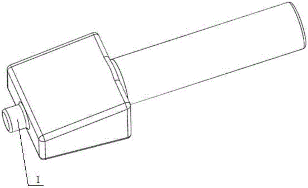
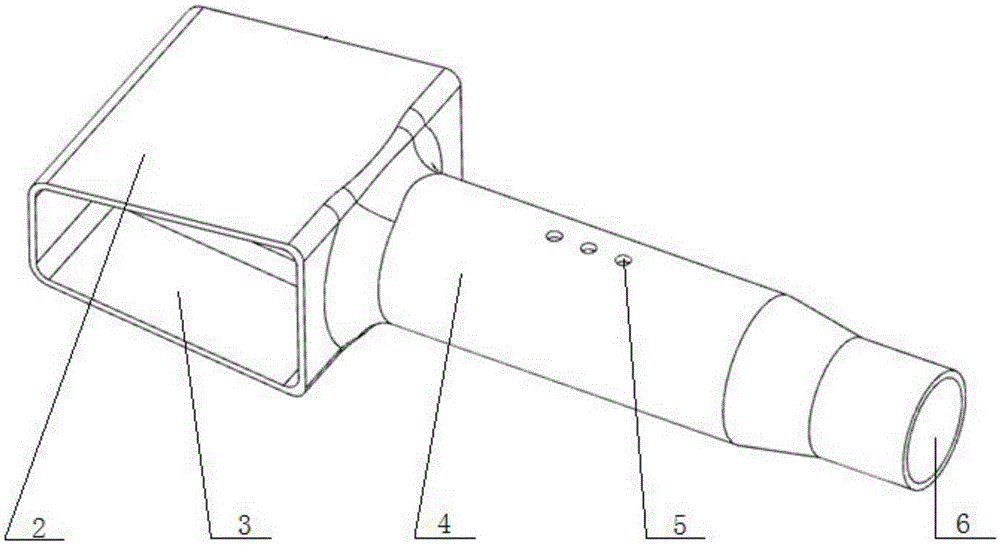
[0020] As shown in the figure: the blank of the special-shaped shaft part is an integral forging, and a process boss 1 is designed on the blank for subsequent processing and clamping. The processing content of special-shaped shaft parts includes structural features such as airfoil 2, deep cavity 3, outer circle 4, radial hole 5, and deep hole 6. The processing process includes the following steps:

[0021] Step 1: Roughing the outer circle 4. First, use the three-jaw chuck of the ordinary lathe to clamp the outer circle of the blank at 4 places, minimize the overhang to reduce vibration, and drill the center hole at the end face of the process boss 1; then, use the three-jaw chuck to clamp the process Boss 1, adjust the center frame so that it is clamped at the outer circle 4 as an auxiliary support to increase the rigidity of the workpiece and reduce the cutting deformation, and drill the center hole on the right end of the blank; finally, adopt the clamping method of one cla...


PUM


Abstract

The invention discloses a turn-milling combination machining process for shaft parts of a special-shaped structure. The process includes the steps that a clamping mode of clamping-ejecting is adopted on a center lathe, so that rough turning of outer circles is carried out; alignment, positioning and clamping are carried out on the center lathe, so that rough milling of wing surfaces is carried out; forged parts are subjected to ultrasonic non-destructive testing, and whether defects exist is tested; deep hole drilling is carried out on the center lathe; rough plunge milling of deep cavities and machining of radial holes are carried out on a numerical control milling machine; semifinishing of the outer circles and boring machining of deep holes are carried out on a numerically controlled lathe; stress relief annealing is carried out on the parts; and the clamping mode of clamping-ejecting is adopted on a turn-milling combination center machine tool, so that finish machining is carried out on the wing surfaces, the deep cavities and the outer circles. According to the turn-milling combination machining process, multiple machining items can be carried out on different machine tools, the utilization rate of the machine tools is increased, and batch production is facilitated; machining procedures are reduced, and production efficiency is improved; finish machining is carried out on a turn-milling combination center, so that positioning errors are reduced, and machining precision is improved.

Description

technical field [0001] The invention relates to a processing technology for special-shaped shaft parts, in particular to a turning-milling composite processing technology for special-shaped shaft parts based on integral forgings, which is applicable to the field of shaft processing and manufacturing with complex structures. Background technique [0002] With the continuous development of the industrial level, the complexity requirements for the shape of shaft parts are also getting higher and higher. Many shaft parts include deep cavity, deep hole, outer circle and radial hole and other structural forms, which have the characteristics of complex structure, high material removal rate, difficult machining, high precision, high value and no scrapping of parts is allowed. At present, the processing method is divided into different sites, with multiple positioning and multiple processes on various machine tools. There are long time for clamping and alignment, too many processes, ...

Claims


Application Information

Patent Timeline
IPC IPC(8): B23P15/00
CPCB23P15/00
Inventor 陈伟张文光傅玉灿崔坤明何磊孙涛孙丹莫建勇
Owner CHENGDU AIRCRAFT INDUSTRY GROUP
Learn More