Solid heat storage directly-heated type heating device

A solid heat storage and heating device technology, applied in heating methods, central heating components, household heating, etc., can solve the problems of excessive energy transmission, difficult adjustment, and large maintenance, and achieve a stable heat exchange process and heat Strong storage capacity and high heat storage temperature

Inactive Publication Date: 2016-03-09
北京谷能中科新能源科技有限公司
View PDF6 Cites 6 Cited by
  • Summary
  • Abstract
  • Description
  • Claims
  • Application Information

AI Technical Summary

Problems solved by technology

This traditional heating method mainly has the following disadvantages: low energy utilization rate, high consumption and serious waste of non-renewable resources, pollution caused by coal or natural gas; excessive hot water delivery radius and energy delivery, difficult adjustment, uneven heating and cooling , and the amount of maintenance is also large, and the installation and operation costs are high; the heating comfort and stability are not strong, and it is not user-operable; due to factors such as equipment, materials, construction, operation, and maintenance, the system leaks, and user damage occurs from time to time. And once it happens, the leakage cannot be stopped immediately, and even other users are implicated because of the problem of one household
Because the heat storage electric heater has no instant heating function, it can only heat the heat storage body first, and then use the heat storage body to dissipate heat for heating, so its convenience in use is limited. Without heat storage, it cannot Realize rapid heating

Method used


Image

  • Solid heat storage directly-heated type heating device
  • Solid heat storage directly-heated type heating device

Examples


Embodiment Construction

[0019] In order to make the object, technical solution and advantages of the present invention clearer, the present invention will be further described in detail below in conjunction with the accompanying drawings and specific embodiments.

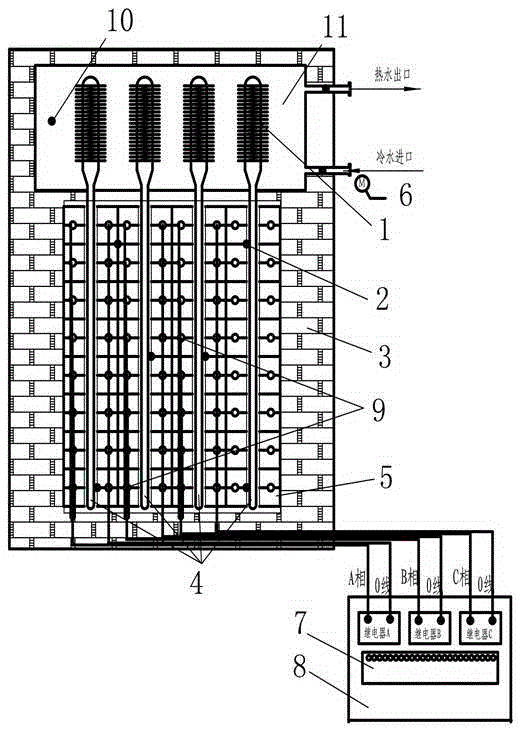
[0020] figure 1 It is a schematic diagram of the overall structure of the solid thermal storage direct heating heating device of the present invention. The present invention is a new type of solid heat storage direct heat heating device, which includes three main parts: solid heat storage pile, heat pipe exchanger and computer control system. The solid heat storage pile is located at the lower part of the direct heat heating device, and the heat pipe exchanger is located at the upper part. The two are combined together, and the outer wall constitutes the overall structure of the direct heating type heating device by the thermal insulation layer 3 .

[0021] The solid heat storage stack includes electric heating tubes 9 , solid heat storag...


PUM


Abstract

The invention provides a solid heat storage directly-heated type heating device. The heating device comprises a solid heat storage pile, a heat pipe exchanger and a computer control system. The solid heat storage pile is located on the lower portion of the directly-heated type heating device, the heat pipe exchanger is located on the upper portion of the directly-heated type heating device, and the outer wall forms an overall structure of the directly-heated type heating device through a heat insulation layer (3). A heat storage system is reasonable in structure, efficient, environmentally friendly, stable, safe, reliable, easy to operate, high in heat storage temperature and stable in heat exchange process, energy is saved, valley point electricity heat storage can be utilized, the heat storage capacity of the whole machine is high, hot water can be instantly released, output is continuous, duration can be guaranteed, zero pollution and zero emission are achieved, and the heating device is suitable for independent large-area central heating of living areas, office buildings, schools, restaurants and the like in the South and North of China.

Description

technical field [0001] The invention relates to a heating device, in particular to a direct heat heating device utilizing solid heat storage. Background technique [0002] Urban heating in winter has always been central heating, using coal or natural gas heating boilers. This traditional heating method mainly has the following disadvantages: low energy utilization rate, high consumption and serious waste of non-renewable resources, pollution caused by coal or natural gas; excessive hot water delivery radius and energy delivery, difficult adjustment, uneven heating and cooling , and the amount of maintenance is also large, and the installation and operation costs are high; the heating comfort and stability are not strong, and it is not user-operable; due to factors such as equipment, materials, construction, operation, and maintenance, the system leaks, and user damage occurs from time to time. And once it happens, the leakage cannot be stopped immediately, and even other us...

Claims


Application Information

Patent Timeline
Patent Type & Authority Applications(China)
IPC IPC(8): F24D15/02F24D19/10
CPCF24D15/02F24D19/1096F24D2200/08F24D2220/10Y02B30/70
Inventor 高忠凡张志新
Owner 北京谷能中科新能源科技有限公司
Why Eureka
Try Eureka