Vibration deep subsoiler

A subsoiler and subsoiler technology, applied in the fields of soil preparation machinery, agricultural machinery and implements, ploughs, etc., can solve the problems of high-power tractors, high mass, increased subsoil cost, and complexity of subsoilers, so as to improve work efficiency, The effect of reducing operating costs and reducing traction resistance

Inactive Publication Date: 2016-03-16
SHIHEZI UNIVERSITY
View PDF0 Cites 19 Cited by
  • Summary
  • Abstract
  • Description
  • Claims
  • Application Information

AI Technical Summary

Problems solved by technology

[0004] At present, medium and high-power tractors are needed for deep loosening of soil. The use of high-power tractors will not only increase the cost of subsoiling, but also high-power tractors have a large mass and are easy to compact the soil; High efficiency and difficult to maintain, the present invention proposes a vibrating subsoiler with simple structure, which has the advantages of light work, small resistance, reliable performance, reasonable structural layout, no too many adjustment parts, less wear parts, and long service life advanced features

Method used


Image

  • Vibration deep subsoiler
  • Vibration deep subsoiler
  • Vibration deep subsoiler

Examples


Embodiment 1

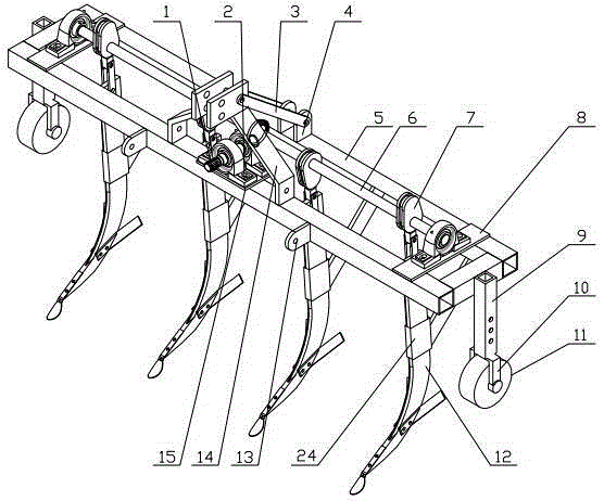
[0021] Embodiment 1: with reference to attached Figure 1 A vibrating subsoiling machine comprising a frame 5, a vibrating subsoiling device, a depth control device and a traction device, characterized in that the vibrating subsoiling device is placed in the middle of the frame 5, the vibrating subsoiling device is connected with the power output shaft of the tractor, and the depth The control device is arranged on both sides of the frame 5, and the traction device is arranged on the front portion of the frame to be connected with the tractor's traction device.

Embodiment 2

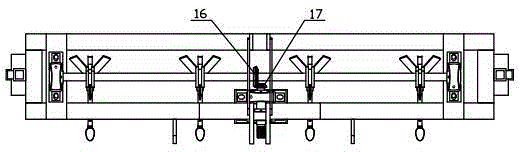
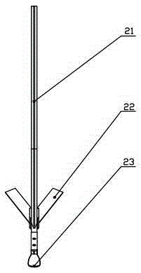
[0023] The difference between this example and Embodiment 1 is that the vibrating subsoiling device includes a power shaft 1, a bearing seat 2, a transmission shaft 6, a cam slider mechanism 7, a support plate 8, a subsoiling shovel 12, a base plate 15, and a driving cone. Gear 16, driven bevel gear 17, slider 19, connector 20, shovel handle 21, wing shovel 22, spoon-shaped shovel tip 23 and reinforcement support plate 24, the above-mentioned power shaft 1 is fixedly installed on the bearing seat 2, and the bearing The seat 2 is installed on the base plate 15, and the base plate 15 is fixed on the front beam of the frame 5. The front end of the power shaft 1 is an octagonal spline shaft end connected with the power output shaft of the tractor, and the driven bevel gear 17 is installed on the power shaft. The rear end of the shaft 1 meshes with the driving bevel gear 16 on the transmission shaft 6, the cam slider mechanism 7 is installed on the transmission shaft 6, the subsoili...

Embodiment 3

[0025] The difference between this example and Embodiment 1 is that the depth control device includes a depth adjuster 9, a wheel frame 10 and a depth gauge wheel 11, and the above-mentioned depth adjuster 9 is vertically connected to the outer surfaces of the left and right sides of the frame 5 respectively. Above, the depth gauge wheel 11 is connected to the wheel frame 10, and the threaded locking holes are distributed on the depth adjuster 9 and the wheel frame 10. The wheel frame 10 is embedded in the depth adjuster 9 and connected by bolts. way to adjust the height of the depth gauge wheel 11.


PUM


Abstract

The invention relates to cultivation machinery loosening soil and deepening cultivation thickness, in particular relates to a vibration deep subsoiler and belongs to the field of agricultural machinery. A vibration deep subsoiler comprises a rack, a vibration deep subsoiling device, depth control devices and a traction device, wherein the vibration deep subsoiling device is arranged in the middle of the rack and connected with a power output shaft of a tractor; the depth control devices are arranged on two sides of the rack; and the traction device is mounted on the front part of the rack and connected with the traction device of the tractor. Cam sliding block mechanisms are employed in the vibration deep subsoiler; I-shaped grooves are formed in the sides of cams; deep subsoilers are connected with the cam sliding block mechanisms; cams are installed on a transmission shaft; the mechanism is compact and simple; each subsoiler tip is in a spoon-shaped structure; wing shovels are arranged on two sides of each subsoiler handle, so soil can be subsoiled and deep subsoiling area can be increased; and the vibration deep subsoiler is suitable for soil deep subsoiling and crop intertillage work.

Description

technical field [0001] The invention relates to a tillage machine for loosening soil and deepening the thickness of a tillage layer, in particular to a vibrating subsoiler, which belongs to the field of agricultural machinery. Background technique [0002] Soil subsoiling refers to the use of a subsoiler to loosen the plow layer 5 to 15 cm below the plow layer, loosen the soil and deepen the thickness of the plow layer. Soil subsoiling is an indispensable mechanized operation item to obtain high yield of crops, and an important technology of soil cultivation, which has been paid more and more attention at home and abroad. [0003] Soil deep loosening technology can break the plow bottom layer and deepen the plow layer thickness. The existence of the bottom layer of the plow prevents the root system of the crops from piercing through, but can only curl and grow above the bottom layer of the plow; the barrier of the bottom layer of the plow prevents precipitation from infiltr...

Claims


Application Information

Patent Timeline
Patent Type & Authority Applications(China)
IPC IPC(8): A01B13/08A01B35/08
CPCA01B13/08A01B35/08
Inventor 李霞张思远汤明军屈通王维新闫毅敏沈晓晨
Owner SHIHEZI UNIVERSITY
Why Eureka
Try Eureka