Needle type porous material emitter array type mini-type field emission electric thruster

A technology of porous materials and electric thrusters, which is applied in the direction of thrust reversers, plasma utilization, machines/engines, etc., can solve the problems of long launch needles, short life of thrusters, and low space utilization, and achieve size reduction and The effect of weight, high thrust density and compact structure

Active Publication Date: 2016-03-16
SHANGHAI INST OF SPACE PROPULSION
View PDF4 Cites 16 Cited by
  • Summary
  • Abstract
  • Description
  • Claims
  • Application Information

AI Technical Summary

Problems solved by technology

[0006] (1) Most of the current pin-type field emission electric thrusters only use a single physical launch needle, the material is generally tungsten, the thrust is small (generally 20-50μN), and the launch needle is long, requiring fine assembly, resulting in the size and weight of the thruster. Larger, in fact, it is difficult to be used for tiny satellites with a weight of less than 10kg, and it is also difficult to be used in occasions that require a large thrust such as orbit transfer
[0007] (2) At present, in order to make the thrust of needle-type field-launched electric thrusters reach the millinewton level to meet the task requirements such as the rapid maneuvering of micro-satellites, a method to increase the thrust is to use multiple field-launched electric thrusters to form an entire column. But it leads to larger weight and size, and it is more difficult to use for tiny satellites weighing less than 10kg
Silicon-based needle array field emission electric thruster The needle array of the field emission electric thruster adopts MEMS etching process, which has high process requirements, and because the temperature of the needle tip is high, but the melting point of silicon is low, the tip of the needle is easily damaged, resulting in a very short life of the thruster , it is very difficult to achieve practical use due to the material bottleneck problem
The crown-shaped porous material tungsten emitter array thruster uses a crown-shaped emitter array to increase the number of emitters, but since the emitters are located on the outer circumference of the crown, there are no emitters in the center of the crown, resulting in a very low density of emitters and low space utilization. Low, and the axial dimension of the crown-shaped emitter array is relatively long, resulting in a relatively large size and weight of the thruster, making it difficult to miniaturize
[0009] (4) The thrust of the slit-type field emission electric thruster is larger than that of the pin-type field emission electric thruster, but due to the complicated process of the structural parts forming the narrow slit, and the large size and weight, the size and weight of the thruster are relatively large, and the actual Difficult to use on microsatellites weighing less than 10kg
[0010] In summary, the current field emission electric thruster structure is difficult to miniaturize, and it is difficult to meet the needs of micro-satellites weighing less than 10kg

Method used


Image

  • Needle type porous material emitter array type mini-type field emission electric thruster
  • Needle type porous material emitter array type mini-type field emission electric thruster
  • Needle type porous material emitter array type mini-type field emission electric thruster

Examples


Embodiment 1

[0039] single gate

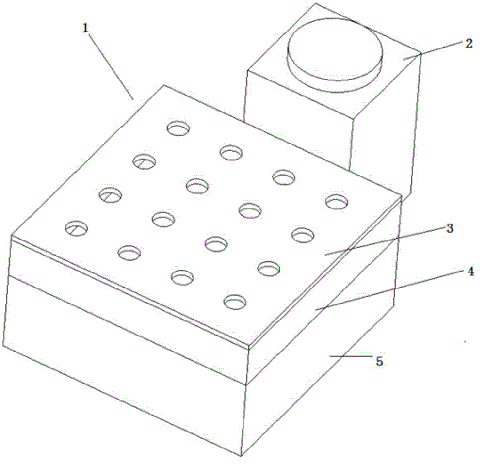
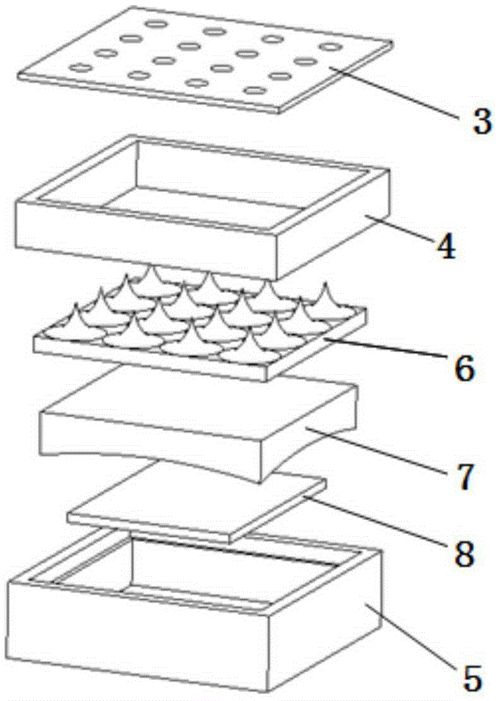
[0040] The needle-type porous material emitter array miniature field emission electric thruster of this embodiment adopts a single grid, such as figure 1 , figure 2 , image 3 shown. The gate has 16 identical gate holes in total, and the gate holes are arranged in a 4×4 manner. The bottom surface of the emitter is flat, and there are 16 emitter needles arranged on the upper surface in a 4×4 manner. The gate holes and emitter pins are distributed accordingly. When working, negative voltage is applied to the grid, positive voltage is applied to the emitter array, and all emitters work at the same time. The neutralizer emits electrons to neutralize the beam. The thruster has a square shape and a small envelope size, which is convenient for installation on tiny satellites.

Embodiment 2

[0042] 16 pins, 4 gates

[0043] The needle type porous material emitter array miniature field emission electric thruster of this embodiment adopts 4 grids. The bottom surface of the emitter is flat, and there are 16 emitter needles arranged on the upper surface in a 4×4 manner. The 4 grids are located in the same plane, and each grid has 4 grid holes arranged in a line, corresponding to 4 emission pins. When working, it is necessary to apply a negative voltage to the working gate, and a positive voltage to the emitter array. When a certain voltage is applied to all four gates, they will work simultaneously to generate the maximum thrust. 1, 2, and 3 grids are combined in different ways and work when a certain voltage is applied to produce thrusts of different sizes and action axes. like Figure 5 shown.

Embodiment 3

[0045] Emitter bottom surface is concave shape

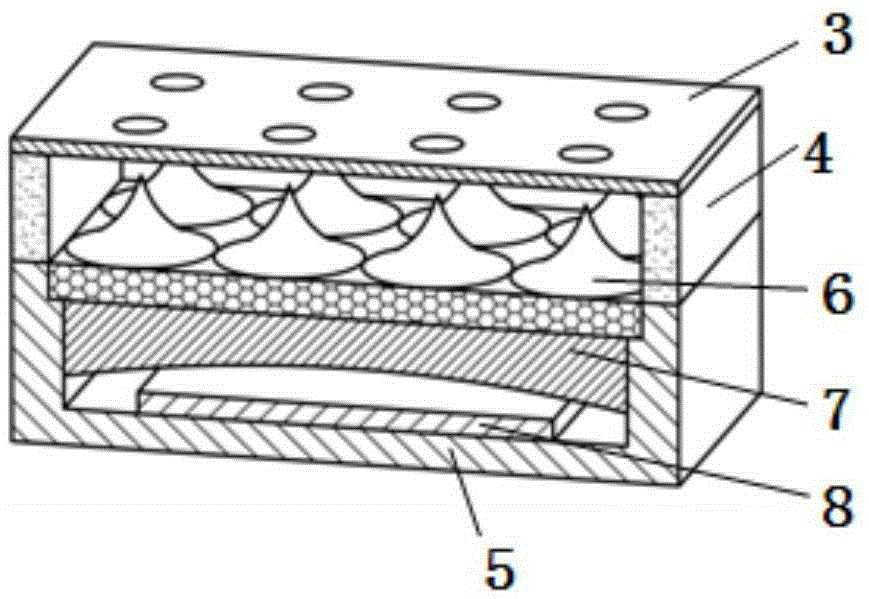
[0046] In the needle-type porous material emitter array miniature field emission electric thruster of this embodiment, the propellant is indium, and the bottom surface of the emitter array is a concave shape ( Image 6 ), to increase the contact surface with the propellant, better store, absorb and transport the propellant. The emitter absorbs the propellant through the surface of the porous material and the tiny gap, and the propellant is transported to the tip of the firing needle through the tiny gap and the surface of the porous material.


PUM


Abstract

The invention discloses a needle type porous material emitter array type mini-type field emission electric thruster. The electric thruster comprises a neutralizer and a thruster main body which are connected with each other, wherein the thruster main body comprises a grid electrode, an insulating bracket and a propellant storage chamber which are sequentially matched and connected with one another from top to bottom; the insulating bracket is of a frame-type structure; an emitter array matched with the grid electrode is arranged inside the insulating bracket; a heater and the propellant which are matched with each other are arranged below the emitter array; the propellant and the heater are both positioned in the propellant storage chamber. The needle type porous material emitter array type mini-type field emission electric thruster disclosed by the invention is small in size, compact in structure, simple in structure, capable of being made into a chip-shaped mini-type thruster, applicable to mini-type satellites and especially applicable to mini-type satellites of which the weight is smaller than 10kg.

Description

technical field [0001] The invention relates to a needle-type emitter miniature field emission electric thruster for a micro-satellite, in particular to a needle-type porous material emitter array miniature field emission electric thruster. Background technique [0002] With the rapid progress of electronic technology and micro-electromechanical system technology, micro-satellites with high functional integration have become a reality and are developing extremely rapidly, especially micro-satellites with a weight of 1-10kg. Due to the short development cycle, low development and launch costs, flexible launch, and difficult detection, micro-satellites can form a "virtual large satellite" in the form of a constellation and form a "virtual large satellite" in the form of a constellation, such as Large-scale remote sensing has been highly valued by countries all over the world, and the number of launches has increased rapidly in recent years. However, at present, most microsate...

Claims


Application Information

Patent Timeline
Patent Type & Authority Applications(China)
IPC IPC(8): F03H1/00
CPCF03H1/0087
Inventor 杭观荣张岩梁伟乔彩霞薛伟华梁爽康小录康小明郭登帅
Owner SHANGHAI INST OF SPACE PROPULSION
Why Eureka
Try Eureka