A crystallizer wiper

A crystallizer and wiper technology, applied in the field of crystallizer wipers, can solve the problems of poor wear resistance and high temperature resistance, high price, increased production cost, etc., achieve good wear resistance and high temperature resistance, reduce use costs, The effect of reducing the number of replacements

Active Publication Date: 2018-03-30
SOUTHWEST ALUMINUM GRP
View PDF8 Cites 0 Cited by
  • Summary
  • Abstract
  • Description
  • Claims
  • Application Information

AI Technical Summary

Problems solved by technology

[0003] However, due to the poor low-temperature plasticity of large-scale ingots of some alloys, if the ingot is directly cooled by the secondary cooling water when it leaves the mold, the axial temperature difference of the ingot will increase, and there will be a tendency of cold cracking, which will affect the ingot. Therefore, when casting this type of alloy, it is necessary to install a mold wiper at the lower edge of the crystallizer. The main part of the mold wiper is an annular rubber sheet, which is located at the lower edge of the mold The inner diameter of the ingot is smaller than the diameter of the ingot. When the ingot moves downward, the inner edge of the rubber flips down and hugs the ingot tightly, so that the part below the bottom of the liquid cavity on the ingot no longer receives water cooling, thereby achieving The purpose of reducing the axial temperature difference of the ingot and reducing the tendency of cold cracking
[0004] At present, there are generally two types of rubber skins used in wipers for crystallizers: one is imported rubber skins, which have better wear resistance and high temperature resistance, but is expensive and expensive to use; the other is domestic rubber skins, which are wear-resistant and resistant The high-temperature performance is poor, and frequent replacement is required, resulting in a short service life of the crystallizer wiper, which affects the normal production, and it is easy to crack the ingot due to the failure of the wiper, resulting in an increase in the scrap rate and an increase in production costs

Method used


Image

  • A crystallizer wiper
  • A crystallizer wiper

Examples


Embodiment Construction

[0024] The invention provides a crystallizer wiper to achieve the purposes of simple structure, convenient maintenance, long service life, and reduced replacement times and use costs.

[0025] The following will clearly and completely describe the technical solutions in the embodiments of the present invention with reference to the accompanying drawings in the embodiments of the present invention. Obviously, the described embodiments are only some, not all, embodiments of the present invention. Based on the embodiments of the present invention, all other embodiments obtained by persons of ordinary skill in the art without making creative efforts belong to the protection scope of the present invention.

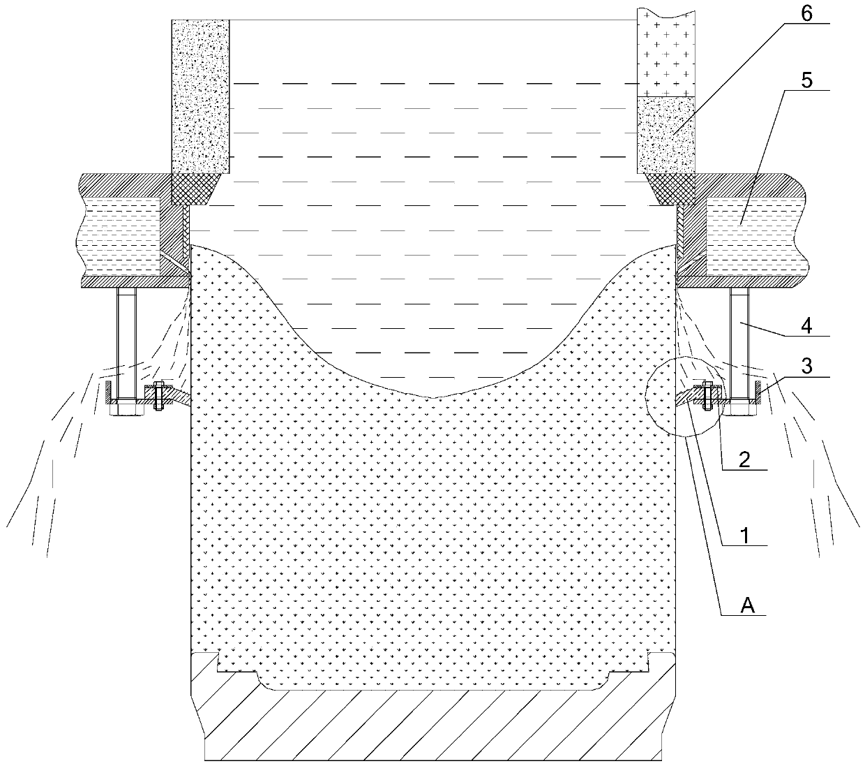
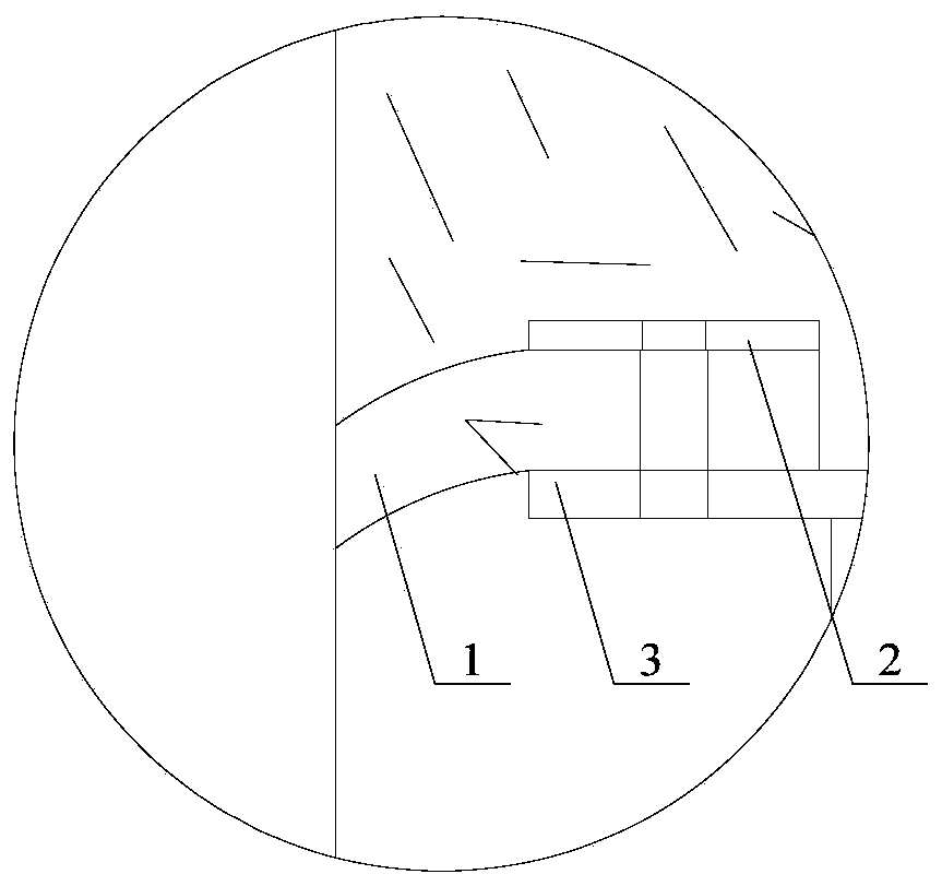
[0026] see figure 1 , figure 1 A cross-sectional view of a crystallizer with a crystallizer wiper provided by an embodiment of the present invention, figure 2 for figure 1 The enlarged schematic diagram of the local structure at A.

[0027] An embodiment of the present inv...


PUM


Abstract

The invention discloses a water wiper for a crystallizer. The water wiper comprises a fixed bracket and a rubber water wiping plate, wherein the fixed bracket is arranged at the lower edge of the crystallizer; the rubber water wiping plate is annular, is fixed on the fixed bracket, and is positioned below the lower edge of the crystallizer; the inner diameter of the rubber water wiping plate is smaller than the diameter of an ingot in the crystallizer; and the rubber water wiping plate comprises the following components in percentage by mass: 2-7% of foaming agent, 1-5% of quartz sand and the balance of fluorine-contained rubber. Rubber, obtained by the formula, is excellent in wear resistance and high-temperature resistance, and is lower in production cost; when the rubber is produced into the rubber water wiping plate to apply to the water wiper for the crystallizer, the water wiper for the crystallizer can be longer in service life, the replacement times are reduced, and the use cost is reduced; and the water wiper for the crystallizer is simple in structure, convenient for production and low in cost.

Description

technical field [0001] The invention relates to the technical field of aluminum alloy melting and casting equipment, in particular to a wiper for a crystallizer. Background technique [0002] Semi-continuous ingot casting is an ingot production process that allows molten metal to pass through the crystallizer continuously to achieve solidification, crystallization and molding. Under the combined action of the wall of the mold and the base of the crystallizer, the crystals are rapidly solidified and a solid solidified shell is formed. When the horizontal liquid level of the molten metal in the mold reaches a certain height, the traction mechanism of the casting machine drives the base and the solidified shell. The solidification shell on the base moves downward continuously and evenly at a certain speed, and the part that has been solidified into an ingot that is separated from the crystallizer is immediately cooled directly by the secondary cooling water from the lower edge ...

Claims


Application Information

Patent Timeline
Patent Type & Authority Patents(China)
IPC IPC(8): B22D11/04C08L101/04C08K3/36C08J9/04
CPCB22D11/04C08J9/04C08K3/36C08L2203/14C08L101/04
Inventor 王剑刁文武杜荣姚勇
Owner SOUTHWEST ALUMINUM GRP
Why Eureka
Try Eureka