Laser machining center

A laser processing and laser technology, applied in the field of mechanical processing, can solve the problems of high tool consumption, low tool service life, cutting heat effect, etc., and achieve the effect of high work efficiency and high processing accuracy

Active Publication Date: 2016-03-23
唐山胜钰机械制造有限公司
View PDF5 Cites 3 Cited by
  • Summary
  • Abstract
  • Description
  • Claims
  • Application Information

AI Technical Summary

Problems solved by technology

[0005] In the machining industry, in the cutting of metal parts or other materials, some materials are particularly difficult to process, such as high-temperature alloys and ceramic materials in the aviation manufacturing industry. The tool life is low during processing, and the cutting quality is not easy to guarantee. , if high-energy lasers can be used to replace traditional cutting tools, it can solve the problems of high cutting tool consumption and cutting heat and cutting force affecting processing quality, and can process materials that are difficult to process by traditional cutting methods, such as glass, ceramics, etc.

Method used


Image

  • Laser machining center
  • Laser machining center
  • Laser machining center

Examples


Embodiment

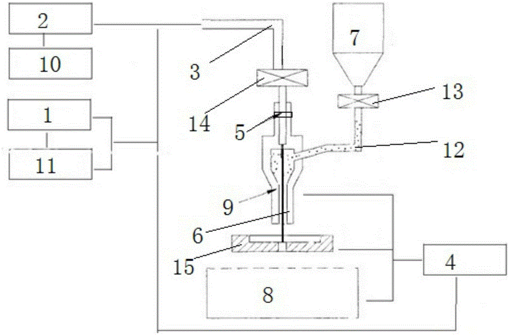
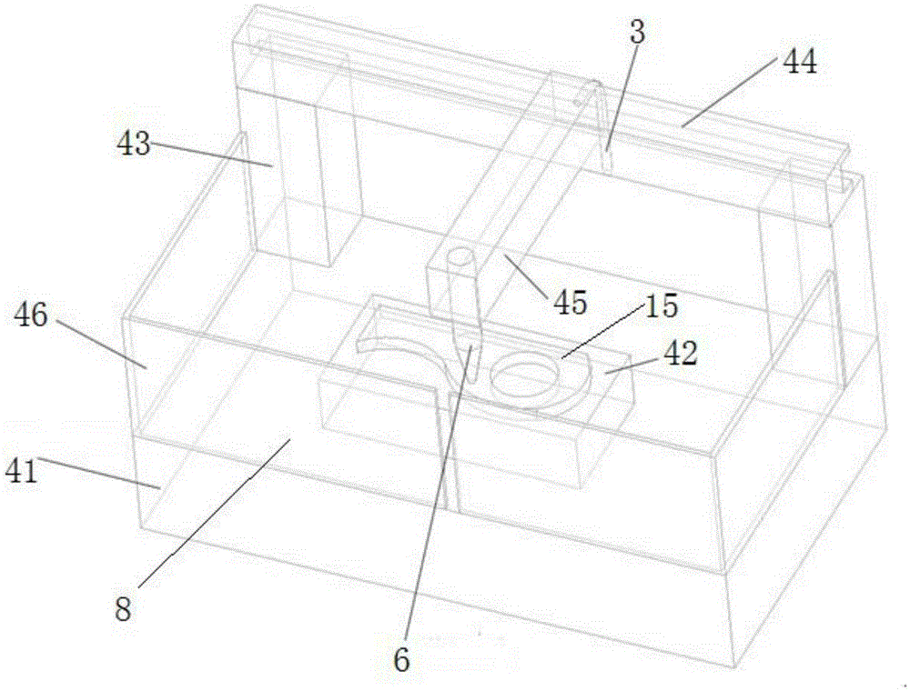
[0027] Embodiment: a laser processing center, including a control system 1, a laser 2, an optical path system 3, a processing machine tool 4, a focusing system 5, a laser cutter head 6, a gas source 7 and a waste receiving device 8, and the laser cutter head is movably installed on On the processing machine tool, the optical path system is connected between the laser and the laser cutter head, the laser cutter head is provided with a protective gas nozzle 9, and the protective gas nozzle is communicated with the gas source, so The condensing system is located between the optical path system and the laser cutter head, the waste material receiving device is located below the laser cutter head, and the laser and the processing machine tool are both communicated with the control system.

[0028] The laser processing center uses high-energy laser beams as processing tools instead of traditional tools, has almost no cutting force, and does not have cooling and lubrication problems. I...

experiment example

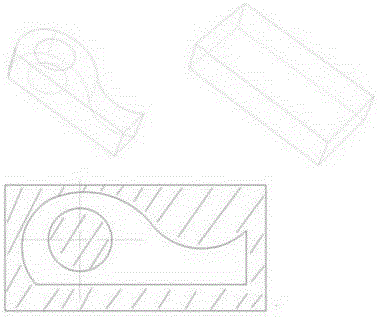
[0041] Experimental example: such as Figure 4 As shown, the blank that needs to be machined is a rectangular piece of raw material. Assuming that the axis of the circular hole is the z-axis direction, for this part, the plane perpendicular to the z-axis direction is obviously the same as any cross-sectional profile within the part range, and the shaded part is the material to be removed for each part. In the case of certain parameters, if the laser beam is moved at a certain scanning speed, and the depth of material removal is h (for example, 0.05mm), then the slicing cad software can be set to slice every h height. Then the control computer scans the blank layer by layer to remove material according to the slice data, and finally obtains the corresponding parts. Of course, this is a special case of equal cross section, and the process for variable cross section is exactly the same, except that the slice thickness at this time will directly affect the final machining accurac...


PUM


Abstract

The invention discloses a laser machining center which comprises a control system, a laser device, an optical path system, a machining tool, a concentrator system, a laser cutter bit, a gas source and a waste receiving device. The laser cutter bit is movably mounted on the machining tool. The optical path system is connected between the laser device and the laser cutter bit. A protective gas nozzle is arranged in the laser cutter bit and communicated with the gas source. The concentrator system is located between the optical path system and the laser cutter bit. The waste receiving device is located below the laser cutter bit, and the laser device and the machining tool are both in communication connection with the control system. The laser machining center is high in working efficiency and machining precision, capable of saving energy and environmentally friendly.

Description

technical field [0001] The invention relates to the field of mechanical processing, in particular to a laser processing center. Background technique [0002] With the advancement of technology, the methods and means of parts processing are becoming more and more diversified. The methods of processing and forming mechanical parts can be divided into two categories from the basic idea. One is the traditional method of gradually removing materials from the whole and finally obtaining finished products. Parts, such as traditional turning, milling, drilling, grinding, planing, etc.; the other is from the perspective of discrete addition, adding materials layer by layer to accumulate the required parts, such as various rapid prototyping methods, sls, lom, fdm, etc. , People follow two kinds of ideas, or combine the two kinds of ideas, and develop various new mechanical processing and forming equipment, such as EDM, wire cutting technology, laser cutting, water jet cutting technolo...

Claims


Application Information

Patent Timeline
Patent Type & Authority Applications(China)
IPC IPC(8): B23K26/38B23K26/70
CPCB23K26/38B23K26/70
Inventor 胡增荣孙茜陈长军张敏王晓南郭华锋徐家乐严凯秦兰兰
Owner 唐山胜钰机械制造有限公司
Why Eureka
Try Eureka