Press quenching mold for locomotive traction gear ring

A technology for locomotives and ring gears, which is applied in the field of press quenching molds for locomotive traction ring gears. It can solve the problems of lower product quality, lower tooth hardness and strength, and no machining allowance, so as to reduce the workload of gear grinding, The effect of reducing elliptical deformation and reducing end face runout

Active Publication Date: 2016-03-23
CRRC QISHUYAN INSTITUTE CO LTD
View PDF6 Cites 7 Cited by
  • Summary
  • Abstract
  • Description
  • Claims
  • Application Information

AI Technical Summary

Problems solved by technology

In actual processing, the carburizing and quenching deformation of ring gears is relatively large, and common distortion types include ellipse, taper, and end face runout. The ring gear distortion leads to no allowance for subsequent processing, and the effective hardened layer depth of the teeth is uneven, which reduces product quality.
The reasons for the deformation of ring gears are more complicated, mainly including raw materials, parts shape, machining volume, heating and cooling processes, etc. These factors affect each other, making it particularly difficult to control ring gear distortion
[0003] In the prior art, there are few control methods for carburizing and quenching distortion of ring gears. The main method is to increase the machining allowance of the gear before carburizing and quenching. The machining allowance is closely related to the raw material and shape, and its control is difficult. It is easy to achieve the ideal allowance, but too large machining allowance will cause the hardness and strength of the tooth to decrease, and, because the root of the tooth is not ground, the excessive grinding of the tooth will cause the tooth root to form Grinding the boss, if the machining allowance is too small, the distortion of the ring gear cannot be reduced, and both of them will easily cause the product to be scrapped

Method used


Image

  • Press quenching mold for locomotive traction gear ring
  • Press quenching mold for locomotive traction gear ring
  • Press quenching mold for locomotive traction gear ring

Examples


Embodiment Construction

[0028] The following will clearly and completely describe the technical solutions in the embodiments of the present invention with reference to the accompanying drawings in the embodiments of the present invention. Obviously, the described embodiments are only some, not all, embodiments of the present invention. Based on the embodiments of the present invention, all other embodiments obtained by persons of ordinary skill in the art without creative efforts fall within the protection scope of the present invention.

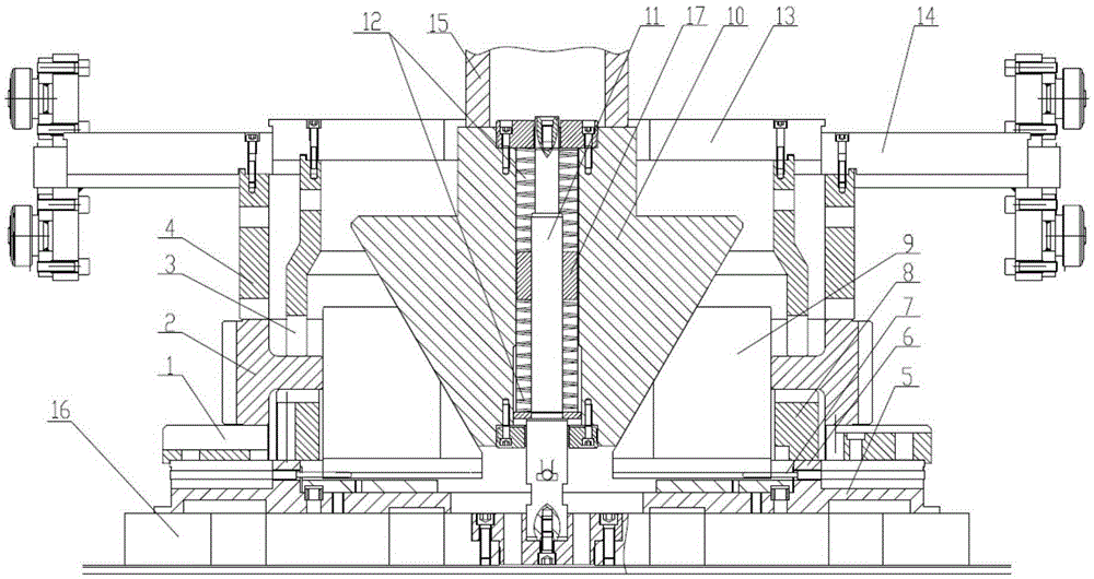
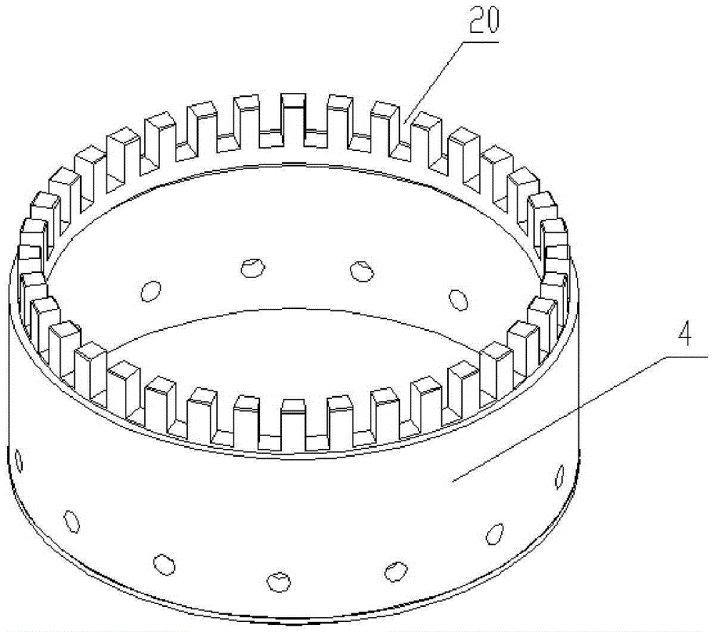
[0029] see figure 1 , the press quenching mold for the locomotive traction ring gear of the present invention is arranged on the workbench 16 of the press quenching machine tool, including an upper mold and a lower mold. The upper mold includes a web die 3 and an end die 4, and the end die 4 is arranged around the outer circumference of the web die 3; the lower die includes an expanding core, a web support platform 8 and an end support platform 1, and the web die 3...


PUM


Abstract

The invention relates to the technical field of thermal treatment molds, in particular to a press quenching mold for a locomotive traction gear ring. The press quenching mold comprises an upper mold body and a lower mold body. The upper mold body comprises a web pressing mold body and an end face pressing mold body. The lower mold body comprises an expanding core, a web supporting table and an end face supporting table. The web supporting table and the web pressing mold body are used for clamping a web of the locomotive traction gear ring; the end face supporting table and the end face pressing mold body are used for clamping the end face of the locomotive traction gear ring; the expanding core comprises a stand column, a circular cone stand, an expander and an expander supporting table; the stand column and the expander supporting table are fixed to a machine tool working table; the circular cone stand is arranged on the stand column in a sleeved mode and can move up and down along the stand column; the expander is arranged around the periphery of the circular cone stand, the bottom of the expander makes contact with the expander supporting table and can perform radial movement on the expander supporting table; the inner inclined surface of the expander is attached to the outer conical surface of the circular cone stand. The press quenching mold for the locomotive traction gear ring is compact in structure and ingenious in design; during carburizing and quenching, the requirement of products for the hardness can be met and deformation of the gear ring due to carburizing and quenching can be effectively controlled; therefore, the qualified rate of the products is increased.

Description

technical field [0001] The invention relates to the technical field of heat treatment molds, in particular to a press-quenching mold for a traction ring gear of a locomotive. Background technique [0002] In order to obtain better anti-fatigue strength, carburizing and quenching is often used as the final heat treatment process for the traction ring gear of railway locomotives. In actual processing, the carburizing and quenching deformation of ring gears is relatively large, and common distortion types include ellipse, taper, and end face runout. The ring gear distortion leads to no allowance for subsequent processing, and the effective hardened layer depth of the teeth is uneven, which reduces product quality. . The reasons for ring gear deformation are more complicated, mainly including raw materials, part shape, machining volume, heating and cooling process, etc. These factors interact with each other, making it particularly difficult to control ring gear distortion. ...

Claims


Application Information

Patent Timeline
Patent Type & Authority Applications(China)
IPC IPC(8): C21D1/673C21D9/32
CPCC21D1/673C21D9/32
Inventor 陈金龙高辉辉黄星吴刚庄军
Owner CRRC QISHUYAN INSTITUTE CO LTD
Why Eureka
Try Eureka