Elastic coupling

An elastic coupling and elastomer technology, applied in the mechanical field, can solve the problems of weak corrosion resistance, reduced dynamic response of shafting, limited compensation ability, etc., and achieves the effect of prolonging service life, strong interference ability and strong compensation ability.

Inactive Publication Date: 2016-03-23
镇江市润州联轴器厂
View PDF5 Cites 0 Cited by
  • Summary
  • Abstract
  • Description
  • Claims
  • Application Information

AI Technical Summary

Problems solved by technology

However this increased torque and stiffness is somewhat offset by increased mass and inertia
Sometimes the negative effects will outweigh its advantages, so that users have to look for other forms of couplings
[0005] As the industry pays more and more attention to the vibration and impact control requirements of power devices, and the situation is getting higher and higher, the existing various types of couplings have exposed their limitations in terms of performance: polymer The elastic parts made of rubber, due to the limitations of the inherent physical and chemical properties of the material itself, affect the performance of the coupling: poor thermal conductivity, narrow operating environment temperature range, short life, due to the low loss factor of the rubber material, no It is beneficial to reduce the dynamic response of the shaft system at the critical speed, the corrosion resistance is weak, and the rubber body is not suitable for working under the state of tensile stress
The rigid characteristics of the elastic couplings in the prior art are basically "hardened" type, the axial and radial offset and the axial inclination angle compensation ability caused by the misalignment of the axis are limited, the assembly process requirements are high, and the operation is inconvenient

Method used


Image

  • Elastic coupling
  • Elastic coupling

Examples


Embodiment Construction

[0016] In order to more clearly illustrate the technical solutions in the embodiments of the present invention or the prior art, the following will briefly introduce the drawings that need to be used in the description of the embodiments or the prior art. Obviously, the accompanying drawings in the following description are only These are some embodiments of the present invention. For those skilled in the art, other drawings can also be obtained according to these drawings without any creative effort.

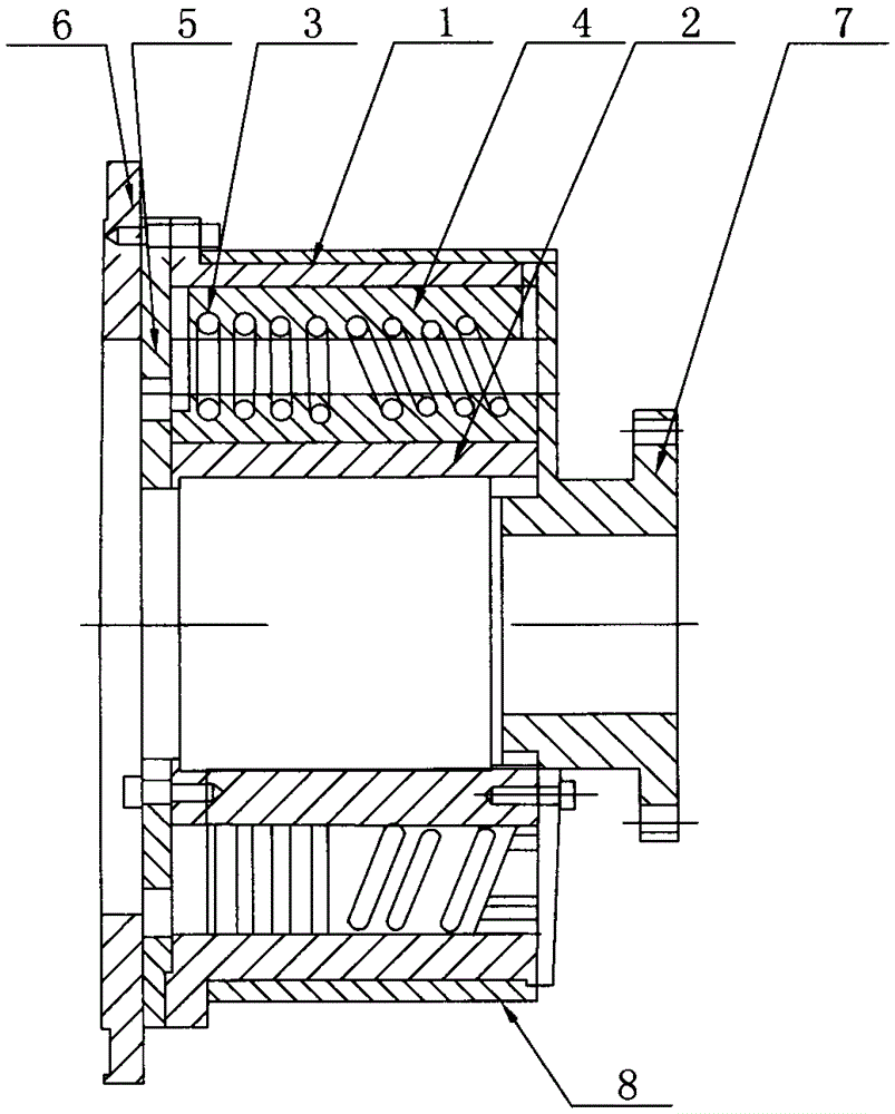
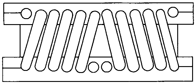
[0017] see as figure 1 —— figure 2 As shown, this specific embodiment adopts the following technical scheme: it includes the active hub body 1, the driven hub body 2, the spiral elastic body 3, the solid connection mechanism 4, the torsion angle limiting device 5, the driving shaft connecting flange 6, the driven Axial flange 7, damping vibration-absorbing ring 8; the active hub body 1 is sheathed on the outer periphery of the driven hub body 2; several spirals are arranged b...


PUM


Abstract

The invention relates to the technical field of machines, in particular to an elastic coupling. The elastic coupling comprises a driving hub body, a driven hub body, spiral elastic bodies, fixed-connection mechanisms, a torsional angle limiting device, a driving shaft connection flange, a driven shaft connection flange and a damping vibration absorption ring. The periphery of the driven hub body is sleeved with the driving hub body, and the multiple spiral elastic bodies are arranged between the inner wall of the driving hub body and the outer wall of the driven hub body; the driving hub body and the corresponding spiral elastic body are connected through the corresponding fixed-connection mechanism, and the driven hub body and the corresponding spiral elastic body are connected through the corresponding fixed-connection mechanism; the torsional angle limiting device is arranged at one end of the driven hub body, and the driven shaft connection flange is connected to the other end of the driven hub body; the driving shaft connection flange is arranged on one side of the torsional angle limiting device; and the damping vibration absorption ring is arranged on the outer wall of the driving hub body, and is a viscous fluid vibration absorption ring. According to the elastic coupling, the compensation capacity of axial and radial deviation and the axial inclination angle is high, the anti-impacting and anti-jamming capability is high, and the service life is prolonged.

Description

technical field [0001] The invention relates to the technical field of machinery, in particular to an elastic coupling. Background technique [0002] Flexible couplings utilize parallel or helical groove systems to accommodate misalignment and transmit torque precisely. Elastic couplings usually have good performance and have price advantages. In many practical applications of stepping and servo systems, elastic couplings are the preferred products. The one-piece design makes the elastic coupling realize the advantages of zero gap transmission torque and no maintenance. There are two basic series of elastic couplings: spiral groove type and parallel groove type. [0003] Features of elastic coupling: (1) One-piece metal elastic body; (2) Zero backlash, synchronous operation; (3) Elastic action to compensate radial, angular and axial deviations; (4) High torque rigidity and excellent sensitivity; (5) The characteristics of clockwise and counterclockwise rotation are exactl...

Claims


Application Information

Patent Timeline
Patent Type & Authority Applications(China)
IPC IPC(8): F16D3/02F16D3/12
Inventor 贡道祥
Owner 镇江市润州联轴器厂
Why Eureka
Try Eureka