Welding machine of inner ring board of steel pipe and application method thereof

An inner ring plate and steel pipe technology, applied in welding accessories, welding equipment, auxiliary welding equipment, etc., can solve the problems of inconvenient welding method of the inner wall ring plate of the steel pipe, increasing the number of pipe butt joints, and increasing the labor intensity of workers, etc. The effect of good welding quality, reduced labor intensity and simple structure

Active Publication Date: 2016-03-30
MCC5 GROUP CORP SHANGHAI
View PDF5 Cites 1 Cited by
  • Summary
  • Abstract
  • Description
  • Claims
  • Application Information

AI Technical Summary

Problems solved by technology

This operation increases the number of pipe butt joints, and when there are more inner ring plates in the pipe, the number of pipe segments will be more, which not only affects the quality of the steel structure, but also increases the labor intensity of the workers
[0004] Therefore there is above-mentioned inconvenience and problem in the welding method of known steel pipe inner wall annular plate

Method used


Image

  • Welding machine of inner ring board of steel pipe and application method thereof
  • Welding machine of inner ring board of steel pipe and application method thereof

Examples


Embodiment 1

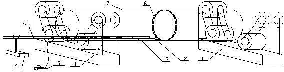
[0031] figure 1 It is a structural schematic diagram of a steel pipe inner ring plate welding machine according to an embodiment of the present invention;

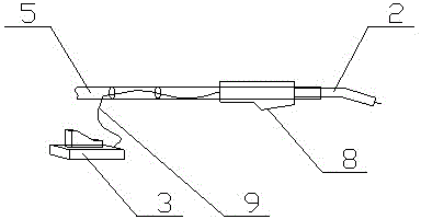
[0032] figure 2 It is a structural schematic diagram of a handle and an arc strike switch according to an embodiment of the present invention. As shown in the figure, the steel pipe inner ring plate welding machine includes a tire rotating mechanism supported on the rotating tire 1 and driving the steel pipe 7 to rotate, a welding torch and a welding torch control mechanism. It is characterized in that: the welding torch control mechanism includes a bracket, Welding handle and arc ignition switch, wherein: the bracket 4 is an iron pier bracket, which is arranged outside the mouth of the steel pipe 7 to be welded; the welding handle 5 is a metal pipe whose length is greater than that of the inner ring plate 6 of the steel pipe and away from the steel pipe 7 One end of the welding handle firmly fixes the welding torch 2, ...

Embodiment 2

[0034] A method for using a steel pipe inner ring plate welding machine, characterized in that it comprises the following steps:

[0035] a. Firmly fix the torch on one end of the handle;

[0036] b. The operator uses the handle to transport the welding torch on one end of the handle to the welding position, and makes the other end of the handle rest on the bracket 4;

[0037] c. Start the tire rotating mechanism supported on the rotating tire 1 and drive the steel pipe 7 to rotate to allow the steel pipe to rotate;

[0038] d. The operator presses the arc ignition switch provided on the welding handle 5 to start welding, and the arc ignition switch (3) is a push-type switch.

[0039] When working, the rotating tire provides power for the steel pipe, and the rotating tire itself is driven by the motor. The rotating tire makes the pipe rotate during welding, which not only effectively prevents the welding torch from moving, but also rotates at a uniform speed to make the weld ...


PUM


Abstract

Provided is a welding machine of an inner ring board of a steel pipe. The welding machine comprises a rotary mechanism, a welding gun and a welding gun control mechanism. The rotary mechanism is arranged on rotary bodies (1) and used for supporting and driving the steel pipe (7) to rotate. The welding machine is characterized in that the welding gun control mechanism comprises a support, a welding handle and a run-on switch; the support (4) is an iron pier support arranged outside of an opening of the welded steel pipe (7); the welding handle (5) is a metal pipe having one end for firmly fixing the welding gun (2) and the other end stretching out of the opening of the welded steel pipe (7) to be placed on the support (4); and the run-on switch (3) is arranged on the welding handle (5).The welding machine of the inner ring board of the steel pipe and the application method thereof have following beneficial effects: the combined welding machine is advantaged by being simple in structure, convenient in operation, uniform in welding seams and fine in welding quality; intensity of labor is reduced; and working efficiency is increased.

Description

technical field [0001] The invention relates to a steel pipe welding device, in particular to a steel pipe inner ring plate welding machine and its use method. Background technique [0002] During the processing of steel structural members, many tubular members are often processed, and designers usually add ring stiffeners at different depths from the inner wall of the steel pipe to the nozzle to strengthen the strength of the steel pipe. [0003] For the welding of the ring plate on the inner wall of the steel pipe with a diameter of more than 800mm, most steel structure manufacturers let the welder directly climb or sit inside the pipe for welding. , the welder can no longer enter the pipe, basically the pipe is cut off at a certain distance from the inner ring plate, so that the inner ring plate is closer to the nozzle to facilitate welding. This operation increases the number of pipe butt joints, and when there are many inner ring plates in the pipe, the number of pipe ...

Claims


Application Information

Patent Timeline
Patent Type & Authority Applications(China)
IPC IPC(8): B23K9/28B23K9/32B23K37/053
Inventor 汝宝祥代玉忠
Owner MCC5 GROUP CORP SHANGHAI
Why Eureka
Try Eureka