Self-concentric brush seal structure with rotor provided with discs

A technology of brush seals and discs, which is applied in the direction of supporting elements of blades, leakage prevention, mechanical equipment, etc., can solve the problem of accelerating brush wire and rotor surface friction, reducing the sealing performance of brush seals, increasing gas leakage, etc. problem, achieve the effect of reducing the stiffening effect and hysteresis effect, improving the performance of the brush seal, and improving the sealing effect

Active Publication Date: 2016-03-30
南京云起共振电力科技有限公司
View PDF6 Cites 4 Cited by
  • Summary
  • Abstract
  • Description
  • Claims
  • Application Information

AI Technical Summary

Problems solved by technology

[0004] Studies have shown that under the action of the high gas pressure difference between the upstream and downstream of the brush filament bundle, the traditional brush seal will bend axially and cling to the rear baffle, and the friction between the brush filament and the rear baffle prevents the brush filament from sealing in time. Deformation, so that the brush wire cannot be deformed in time to follow the speed-up of the rotor or the increase in vortex eccentricity, resulting in the stiffening effect of the brush wire
The stiffening effect will cause accelerated wear of the brush wire and the rotor raceway, reducing the sealing performance of the brush seal and shortening the service life
In addition, as the rotor slows down or returns to a smaller vortex eccentric position, the friction between the brush filament and the rear baffle prevents the brush filament from recovering immediately, and the brush filament

Method used


Image

  • Self-concentric brush seal structure with rotor provided with discs
  • Self-concentric brush seal structure with rotor provided with discs
  • Self-concentric brush seal structure with rotor provided with discs

Examples


Embodiment Construction

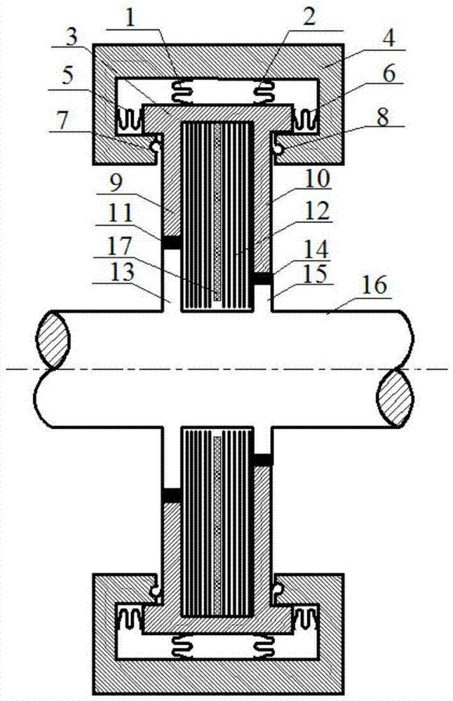
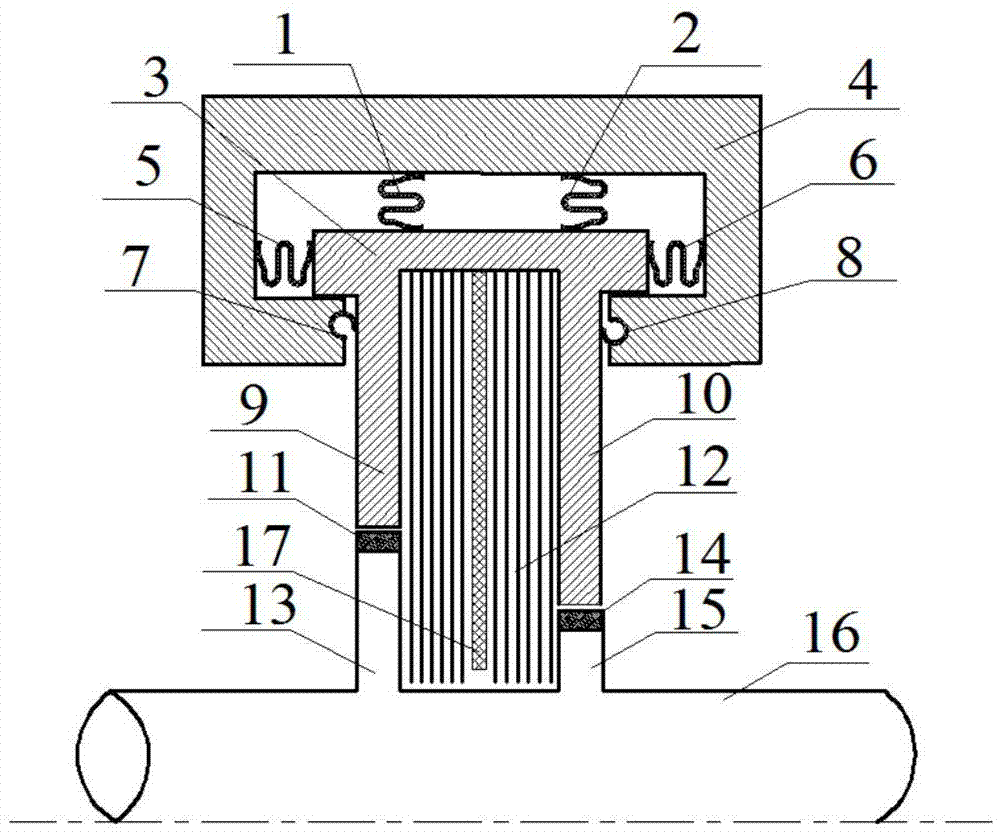
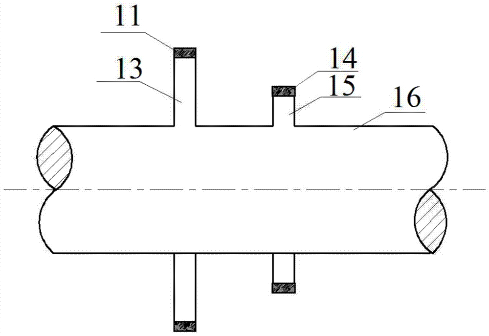
[0024] Such as Figure 1-Figure 3 Shown: a self-concentric brush seal structure with discs in the rotor, including radial W-shaped seal rings 1 and 2, welding zone 3, stator case 4, axial W-shaped seal rings 5 ​​and 6, C Type sealing ring 7,8, front baffle plate 9, back baffle plate 10, wear-resistant coating 11,14, brush wire bundle 12, front disc 13, rear disc 15, rotor 16, bearing plate 17. The brush seal is composed of a welding zone 3, a front baffle 9, a rear baffle 10 and a brush wire bundle 12, and a certain radial gap is maintained between the brush seal and the stator casing 4 to ensure that the brush seal Can move radially freely; C-shaped sealing rings 7 and 8 are located on the neck surface of the front and rear baffles to cooperate with the stator casing 4, and the openings of C-shaped sealing rings 7 and 8 are connected with the high-pressure side, self-expanding under the action of pressure difference, A good seal is achieved. The pressure bearing plate 17 is...


PUM

PropertyMeasurementUnit
Diameteraaaaaaaaaa
Lengthaaaaaaaaaa
Thicknessaaaaaaaaaa

Abstract

A self-concentric brush seal structure with a rotor provided with discs comprises a brush seal part composed of a fusion welding area, a front baffle, a rear baffle and a brush wire bundle, a stator box, C-shaped seal rings, W-shaped seal rings, wear-resistant coatings, a bearing plate, the front disc, the rear disc and the rotor. The C-shaped seal rings are embedded into the neck surfaces of the front baffle and the rear baffle and are matched with the stator box. The W-shaped seal rings are clamped in the axial direction and the radial direction through the brush seal part and the stator box. The front disc is located at the lower end of the front baffle and is vertically fixed to the surface of the rotor, and the rear disc is located at the lower end of the rear baffle and is vertically fixed to the surface of the rotor. The self-concentric brush seal structure is simple; compared with traditional fixed brush seals, the self-concentric brush seal structure has the advantages that the brush seal part can move freely in the radial direction by being clamped in the stator box through the C-shaped seal rings and the W-shaped seal rings and can move along with the rotor for keeping self-concentric when the rotor moves in the radial direction, and continuous damage caused by direct rubbing between the rotor and the brush seal part can be avoided.

Description

technical field [0001] The invention relates to a dynamic sealing structure applied to rotating machines, in particular to a self-concentric brush-type sealing structure with discs in the rotor. Background technique [0002] Brush seals are key components of rotating machinery such as aero-engines, steam turbines, and compressors. Compared with the traditional labyrinth seal, the brush seal not only has better sealing characteristics, but also is a flexible contact dynamic sealing technology, which can adapt to the instantaneous radial deformation or eccentric movement of the rotor. In addition, the brush wire of the brush seal The flexible contact with the rotor shaft can improve the vibration characteristics of the rotor system and ensure the safety of the unit operation. Therefore, brush seals are widely used in rotating machinery in aerospace, electric power, petrochemical and other industries. [0003] The brush seal is composed of the front baffle, the rear baffle and...

Claims


Application Information

Patent Timeline
IPC IPC(8): F01D5/28F01D11/00F01D11/08
CPCF01D5/28F01D11/003F01D11/08F05D2300/224F05D2300/432
Inventor 孙丹刘宁宁赵欢艾延廷
Owner 南京云起共振电力科技有限公司
Why Eureka
Try Eureka