Electric contact point and contact element

A technology of electrical contacts and contacts, which is applied in the direction of contacts, contact materials, circuits, etc., can solve the problems of increased arc generation and increased consumption of electrical contact materials, and achieves reduced consumption and low-cost opening and closing Equipment, the effect of shortening the duration of tremors

Active Publication Date: 2016-03-30
TOKURIKI HONTEN
View PDF7 Cites 2 Cited by
  • Summary
  • Abstract
  • Description
  • Claims
  • Application Information

AI Technical Summary

Problems solved by technology

[0007] When this chattering phenomenon occurs, the number of arcs generated between electrical c...

Method used


Image

  • Electric contact point and contact element
  • Electric contact point and contact element
  • Electric contact point and contact element

Examples


Embodiment 1

[0043] A silver alloy material having a composition of 91Ag-5.8Sn-3In-0.2Ni in mass % was produced by a dissolution method, and rolling and annealing were repeated to obtain a desired sheet. In addition, in the present invention, as long as it is a silver alloy such as an Ag-Ni alloy or an Ag-W alloy used as an electrical contact material, or an internal oxidation treatment is performed in a post-process to form a silver oxide electrical contact material material, any silver alloy material can be used.

[0044] Form a kind of composite material, and this composite material is to be compounded as the pure silver plate that the thickness of pure silver layer 2 is 3~30% of the total thickness of electric contact on one side of this plate and forms. In addition, in the present invention, when the pure silver layer 2 is less than 3% of the thickness of the electrical contact layer, the bonding strength with the functional layer is not ideal; , the bonding strength was not found to...

Embodiment 2

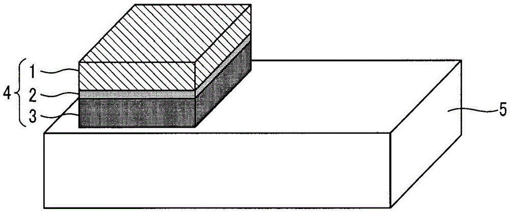
[0048] In the same way as in Example 1, the contacts (figure 1 ) (Types of electrical contacts No.6~10). Furthermore, the functional layer has a Vickers hardness of 94 and the base material of the contact has a Vickers hardness of 140.

Embodiment 3

[0050] Using the composite material obtained by the same method as in Example 1, a disc-shaped composite material of 10 mmφ was obtained by press punching.

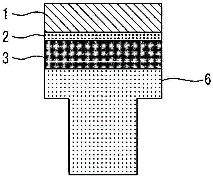
[0051] The 10mmφ composite material obtained in this way is subjected to barrel polishing and internal oxidation treatment, and the functional layer 3 is made of oxygen-free Cu (Vickers hardness 74) with a thickness of 1 to 50% of the total thickness of the electrical contact. After the plate is bonded to the composite material, it is brazed with a rivet-shaped base material 6 composed of oxygen-free Cu (Vickers hardness 110) to form an electrical contact ( figure 2 ).

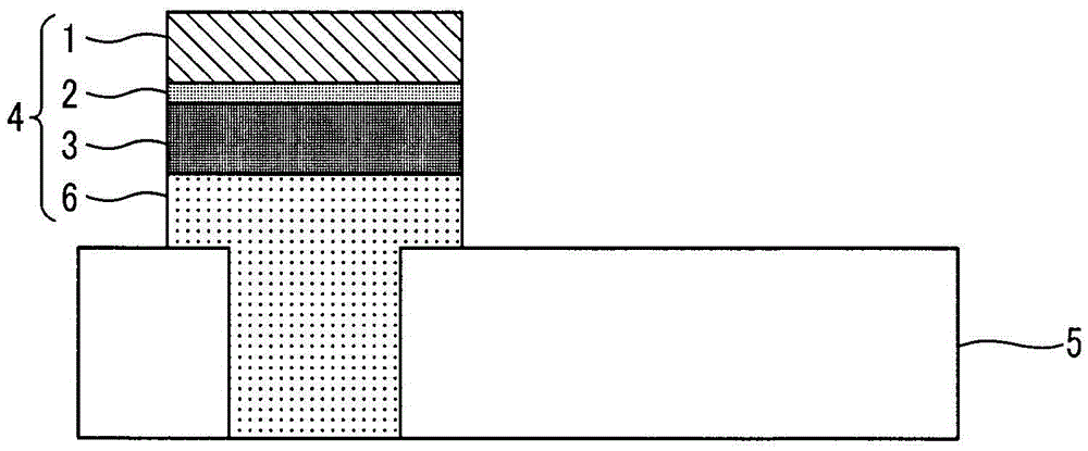
[0052] Such an electrical contact 4 is riveted and joined by a rivet-shaped base material 6 to a contact base material 5 made of oxygen-free Cu (Vickers hardness 110) to form a contact ( image 3 ) (Types of electrical contacts No.11~15).


PUM


Abstract

[Problem] An arcing horn, or the like, for guiding an arc occurring when opening/closing an electric contact thereby preventing erosion of the contact point or a support material, or, a protruding portion of the support material provided at an extremity portion of the contact point in the direction in which the arc is driven thereby rendering the contact point difficult to melt, are known ways in prior art to prevent detachment and erosion. However, as these methods are only realizable if sufficient space can be secured for an arc-extinguishing chamber, or if sufficient dimensions of the support material can be secured, these methods are not necessarily adoptable if a device is to be reduced in size. [Solution] The present invention is characterized in that an electric contact point and a contact element having improved resistance to erosion are achieved by a reduction in the amount of erosion at the electric contact point, comprising pasting onto the surface of a pure silver layer on the back side of a contact point where detachment and erosion readily progress, a copper or a copper alloy having excellent electric conductivity, heat conductivity and mechanical strength as a functional layer, thereby conferring to the functional layer a function of transmitting to a support material the heat generated when opening/closing the electric contact, a function of shortening the duration of chattering, and a function of preventing detachment and erosion, or the like, by maintaining the strength of the bond with the support material.

Description

technical field [0001] The present invention relates to electrical contacts and contacts that can be used in contact control devices such as circuit breakers or electromagnetic switches. Background technique [0002] For switching equipment such as electromagnetic switches, in order to realize the long life of the equipment, it is the shortest way to improve the consumption resistance of the electrical contact material itself and make it longer. Therefore, it is necessary to improve the electrical contact material itself. Various research and development related to wear resistance performance. [0003] Among them, the method of joining the electrical contact material and the base material of the contact and its joining state are known, especially when the switching frequency is high and the service life is strongly required to be extended, such as electromagnetic switches and relays. Whether it is good or not has a great impact on the life of the electrical contact material...

Claims


Application Information

Patent Timeline
IPC IPC(8): H01H1/04
CPCH01H11/041H01H1/0231H01H1/02372H01H1/025
Inventor 汲田英生真真田慎也石泽阳介内田有祐
Owner TOKURIKI HONTEN
Why Eureka
Try Eureka