
Added material manufacturing method under vibration condition

An additive manufacturing and condition technology, applied in the field of arc wire feeding additive manufacturing and laser powder feeding melting additive manufacturing, can solve the problems affecting the machining accuracy of parts, parts cracking, inclusions, etc., to improve the quality and yield, eliminate the Porosity and inclusions, residual stress relief effect

Active Publication Date: 2016-04-06
HUAZHONG UNIV OF SCI & TECH
View PDF13 Cites 34 Cited by
  • Summary
  • Abstract
  • Description
  • Claims
  • Application Information

AI Technical Summary

Problems solved by technology

Larger internal stress will cause deformation, which will affect the processing accuracy of the parts. When the internal stress is too large, it will even cause the parts to crack and be scrapped.
[0006] To sum up, if the control is not proper, defects such as pores, inclusions, deformation and cracking will occur during the additive manufacturing process.

Method used


Image

  • Added material manufacturing method under vibration condition

Examples


Embodiment 1

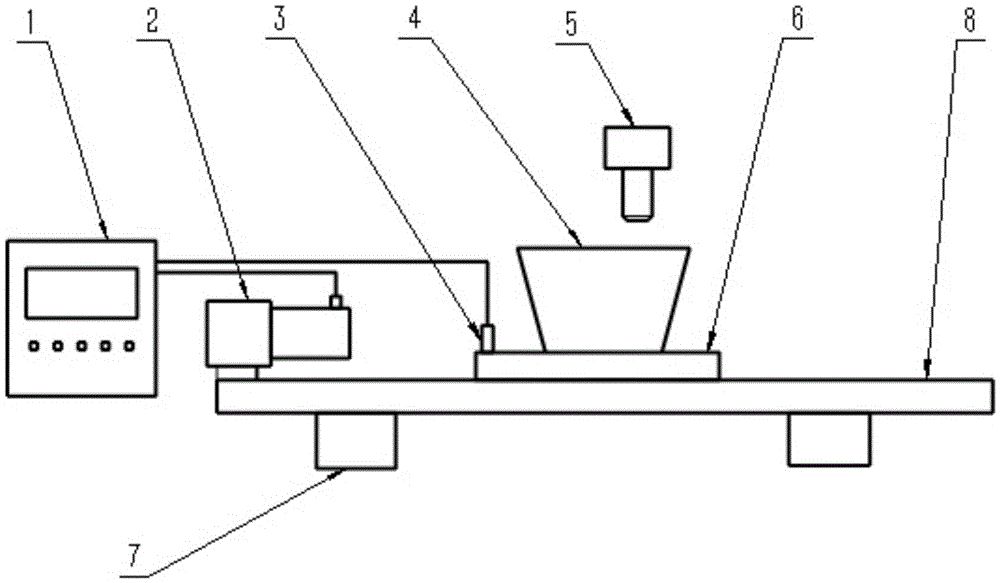
[0035] As mentioned above, the selected additive manufacturing method for additive manufacturing under vibration conditions is arc wire feeding additive manufacturing. The exciter is an eccentric motor, and its working time and vibration acceleration are set through the vibration control cabinet; the selected filler material is 1.0 mm in diameter. mm ER85-G high-strength steel welding wire, the corresponding best vibration acceleration is 17m / s 2 , the vibrating platform is made of rigid material, the material is Q235 rolled steel plate, the wire feeding speed is 4m / min, the welding speed is 3mm / s, the eccentric angle of the eccentric motor is 20°, and the corresponding motor speed is 2268r / min, The size of the vibration platform is 2700mm×800mm×50mm,

[0036] (1) Preparatory work, fixing the eccentric motor and the additive manufacturing substrate on the vibration platform, the vibration platform is made of rigid materials; where four rubber pads are placed under the vibratio...

Embodiment 2

[0041] As mentioned above, the selected additive manufacturing method for additive manufacturing under vibration conditions is arc wire feeding additive manufacturing. The exciter is an eccentric motor, and its working time and vibration acceleration are set through the vibration control cabinet; the selected filler material is 1.2 in diameter. mm aluminum-magnesium alloy welding wire, the vibrating platform is made of rigid material Q235 rolled steel plate, the wire feeding speed is 9.4m / min, the welding speed is 6mm / s, the eccentric angle of the eccentric motor is 20°, the rotational speed of the motor 2300r / min, the vibration acceleration of the substrate placement position is 20m / s 2 , the size of the vibration platform is 2700mm×800mm×50mm,

[0042] (1) Preparatory work, fix the exciter and the additive manufacturing substrate on the vibration platform, the vibration platform is made of rigid materials; where four rubber pads are placed under the vibration platform, and t...


PUM


Abstract

The invention proposes an added material manufacturing method under a vibration condition. In an arc wire feeding added material manufacturing or laser powder feeding melting added material manufacturing process, mechanical vibration with a certain frequency is synchronously introduced, so that parts are located in a micro vibrating state; and the mechanical vibration acts on a micro liquid-state molten bath formed in the added material manufacturing process to refine grains, so that the structure becomes more uniform, and such phenomenon as air holes, inclusions and incomplete fusion is reduced or even eliminated. Meanwhile, the vibration acts on metal just condensed, so that the stress generated by vibration and residual stress generated in the added material manufacturing process are superposed to generate local plastic deformation to achieve the purpose of reducing residual stress and deformation of added material manufacturing parts, and the added material manufacturing parts under vibration condition are more excellent in performances.

Description

technical field [0001] The invention belongs to the field of additive manufacturing, and more specifically is a method suitable for arc wire feeding additive manufacturing and laser powder feeding melting additive manufacturing. The platform is vibrated by an exciter installed on the additive manufacturing platform, In this way, the additive manufacturing forming is completed synchronously during the vibration process. Background technique [0002] Laser powder feeding melting additive manufacturing and arc wire feeding additive manufacturing are a new type of manufacturing technology based on the principle of layer-by-layer accumulation of discrete materials, and based on the product's 3D CAD model, by adding filling materials to accumulate product prototypes or parts layer by layer . Laser powder-fed melting additive manufacturing uses metal powder as the filling material, and arc wire-feeding additive manufacturing uses metal wire as the filling material. Both methods ca...

Claims


Application Information

Patent Timeline
IPC IPC(8): B22F3/115B22F3/105B33Y10/00
CPCB22F3/115B22F2202/01B22F10/00B22F12/22B22F12/30B22F10/25Y02P10/25
Inventor 王福德曾晓雁曹嘉明高明李玉飞谢勇亢凯
Owner HUAZHONG UNIV OF SCI & TECH
Learn More