Regenerative radiant tube burner with flue gas recirculation

A regenerative radiant tube and flue gas technology, applied to gas fuel burners, burners, combustion methods, etc., can solve the problems of high exhaust gas temperature, poor energy saving effect, and large energy consumption, and achieve low exhaust gas temperature , reduce pollution, good temperature uniformity

Active Publication Date: 2016-04-06
FOSHAN KEHAO COMBUSTION EQUIP MFG
View PDF6 Cites 11 Cited by
  • Summary
  • Abstract
  • Description
  • Claims
  • Application Information

AI Technical Summary

Problems solved by technology

Since the radiant tube combustion process generally only adopts simple heat exchange technology, the exhaust gas temperature is high, the energy consumption is large, and the energy saving effect is poor.

Method used


Image

  • Regenerative radiant tube burner with flue gas recirculation
  • Regenerative radiant tube burner with flue gas recirculation

Examples


Embodiment Construction

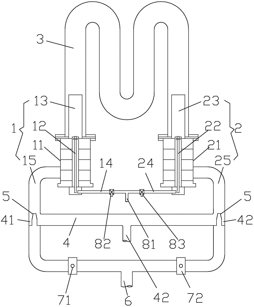
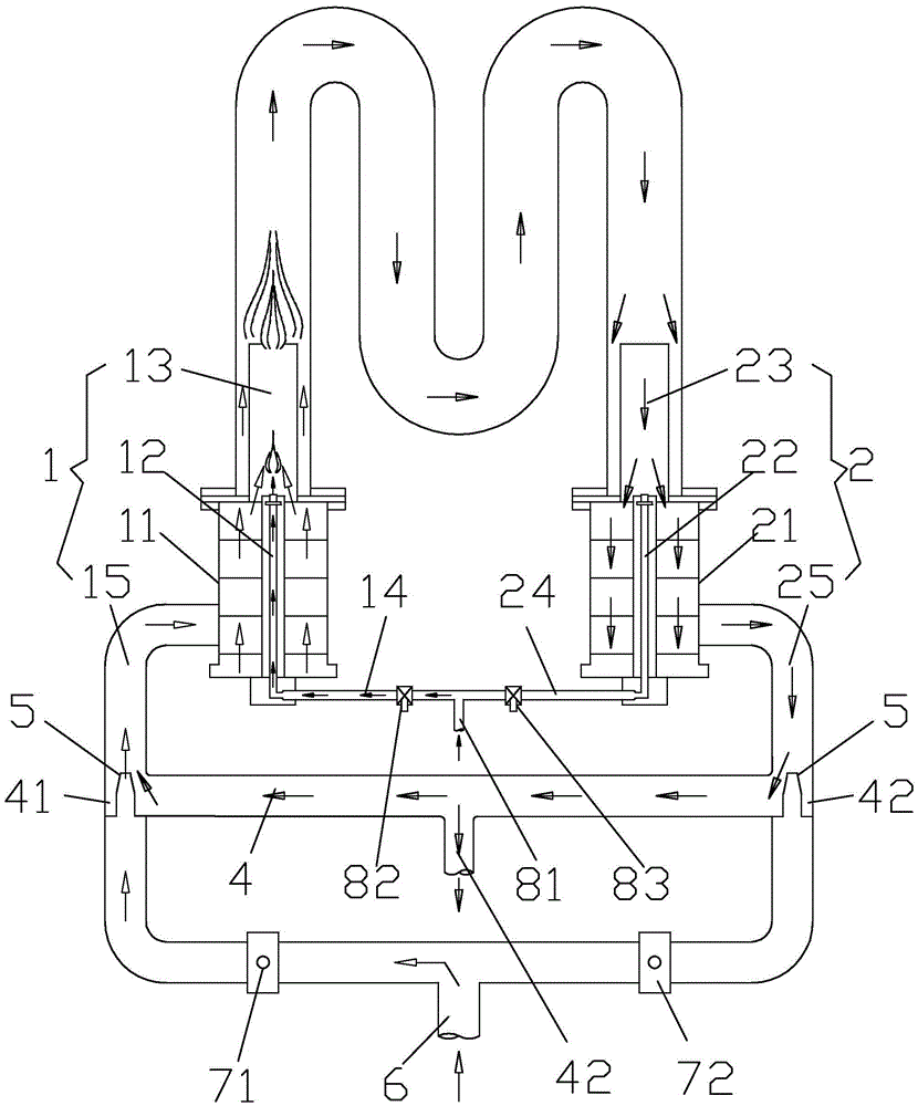
[0014] refer to Figure 1 to Figure 2 A regenerative radiant tube burner with flue gas reflow provided in this embodiment includes first and second burners 1 and 2, and the two burners are used in pairs and installed at both ends of the radiant tube 3 respectively. The first and second burners 1 and 2 have the same structure, and the first burner 1 includes a first heat storage body 11, a first burner core 12 passing through the first heat storage body 11, and a first burner core 12 located at the first burner The first air conduit 13 at the front end of the nozzle core 12, one end of the first burner core 12 is connected to the first gas pipeline 14, the first air conduit 13 is connected to the first air pipeline 15, and the second burner 2 includes The second heat storage body 21, the second burner core 22 passing through the second heat storage body 21, the second air duct 23 located at the front end of the second burner core 22, one end of the second burner core 22 is conn...


PUM


Abstract

The invention discloses a regenerative radiant tube burner with flue gas recirculation. The regenerative radiant tube burner comprises a first burner body and a second burner body; the first burner body comprises a first regenerative body, a first burner core penetrating through the first regenerative body and a first air conduit located at the front end of the first burner core, one end of the first burner core is connected with a first gas pipeline, and the first air conduit is connected with a first air pipeline; the second burner body comprises a second regenerative body, a second burner core penetrating through the second regenerative body and a second air conduit located at the front end of the second burner core, one end of the second burner core is connected with a second gas pipeline, and the second air conduit is connected with a second air pipeline; the first air pipeline and the second air pipeline are mutually communicated to form a circulating pipeline which is provided with an air inlet and a flue gas outlet. By means of the regenerative radiant tube burner with flue gas recirculation, the oxygen content of burning supporting air can be decreased, the flame temperature during burning can be decreased, emission of NOx is greatly reduced, and pollution to the atmosphere in the burning process is reduced.

Description

technical field [0001] The invention relates to a radiant tube burner, in particular to a regenerative radiant tube burner with flue gas backflow. Background technique [0002] As early as the mid-nineteenth century, the regenerative combustion technology was applied, but due to its large area occupied by the regenerator, long reversing time, and complicated operation, it was gradually replaced by other combustion technologies. It was not until the 1980s that the miniaturization of the regenerator and the shortening of the reversing time made the regenerative combustion technology develop to a certain extent. The working principle of the regenerative combustion technology is: the regenerative burners are arranged in pairs, using the regenerator as the carrier, alternately heated by the heat of the exhaust gas, and then the heat stored in the regenerator is used to heat the air or gas. The heating body periodically heats and releases heat to preheat the air or gas to a high ...

Claims


Application Information

Patent Timeline
Patent Type & Authority Applications(China)
IPC IPC(8): F23D14/04F23D14/12F23D14/48F23D14/66F23D14/46
CPCF23D14/04F23D14/125F23D14/46F23D14/48F23D14/66F23D2203/005Y02E20/34
Inventor 王建中潘映沛颜磊
Owner FOSHAN KEHAO COMBUSTION EQUIP MFG
Why Eureka
Try Eureka