ka band microstrip line gain equalizer

A gain equalizer, microstrip line technology, applied to the circuit components of transit time type electron tubes, etc., can solve the problems of increasing the difficulty of system integration, occupying a large area, and deteriorating circuit reliability, etc., and achieves excellent standing wave performance. Compact structure, excellent balance effect

Active Publication Date: 2017-08-04
10TH RES INST OF CETC
View PDF5 Cites 0 Cited by
  • Summary
  • Abstract
  • Description
  • Claims
  • Application Information

AI Technical Summary

Problems solved by technology

To achieve a large amount of equalization, multi-level cascading is required, which takes up too much area, increases the difficulty of system integration, deteriorates the reliability of the circuit, and brings a lot of inconvenience to the application.

Method used


Image

  • ka band microstrip line gain equalizer

Examples


Embodiment Construction

[0013] The present invention will be further described below in conjunction with drawings and embodiments.

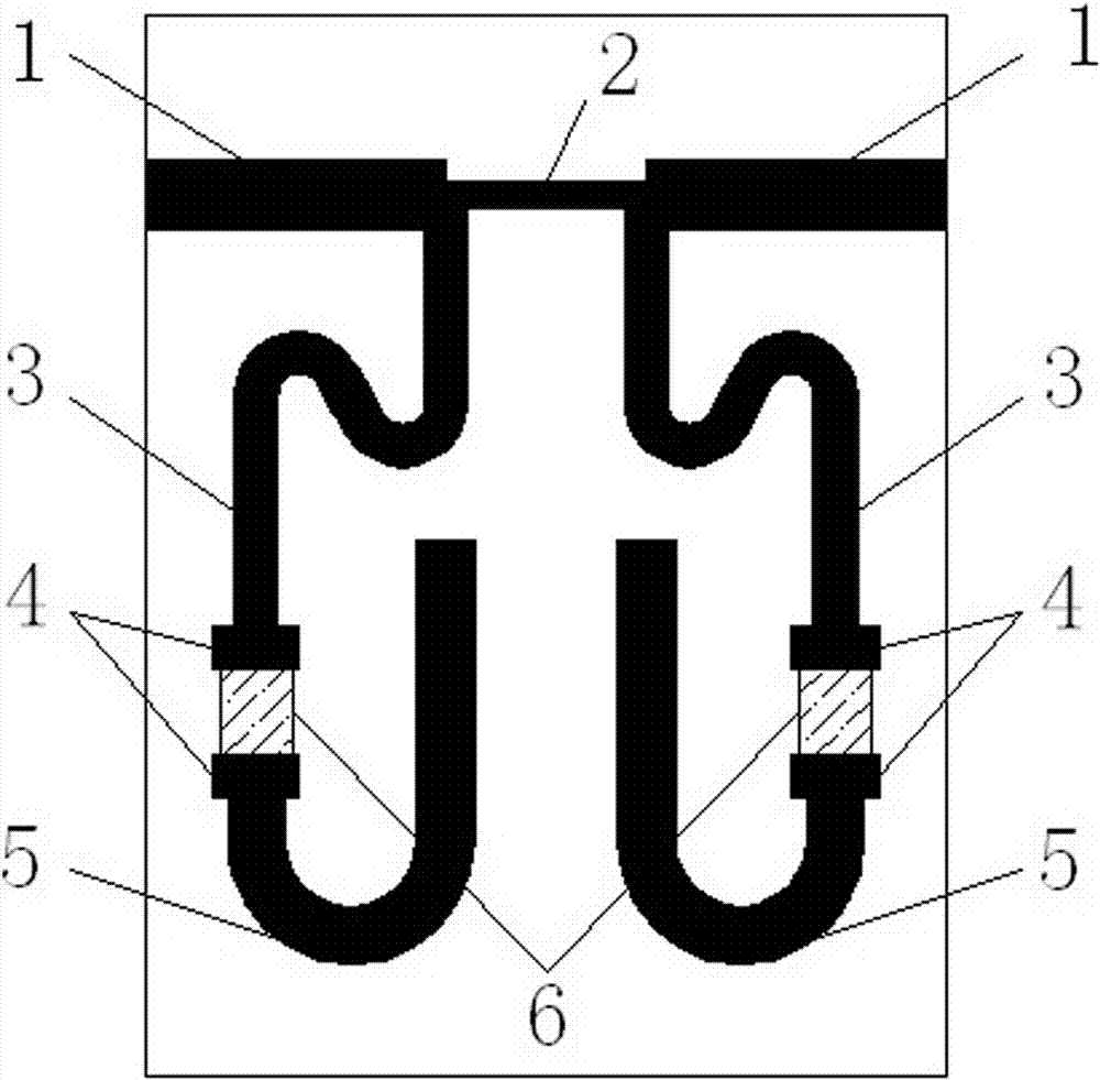
[0014] refer to figure 1 . In the embodiment described below, a Ka-band microstrip line gain equalizer includes two sections of 50Ω microstrip line 1, impedance matching microstrip line 2, high-impedance microstrip line 3, widened microstrip line 4, microstrip line With open circuit stub 5 and thin film resistor 6. A high-resistance microstrip line 3 is set between the thin film resistor 6 and the main transmission line, and a wider microstrip open branch 5 is behind the thin film resistor 6 . The high-resistance microstrip line 3 is bent into an S shape, and the microstrip open stub 5 is bent into a U shape. The actual thin film circuit size of this embodiment is 2.9mm×3.7mm.

[0015] The main microwave signal transmission line is composed of an impedance matching microstrip line 2 in the middle and two 50Ω microstrip lines 1 on both sides. Both sides of the imped...


PUM


Abstract

The invention proposes a Ka-waveband microstrip line gain equalizer, and aims to provide an equalizer which is compact in structure and can be used for achieving high equilibrium quantity and improving amplitude-frequency response of a transceiving front end. The Ka-waveband microstrip line gain equalizer is implemented according to the following scheme: two segments of 50-ohm microstrip lines (1) are connected respectively from horizontal ports of T-shaped joints at the two sides of an impedance matching microstrip line (2) to form a main transmission line and also serve as an input end and an output end of a microwave signal; two microwave resonant units axially symmetric to each other along a vertical central line comprise high-resistance microstrip lines (3), widened microstrip lines (4), thin-film resistors (6) and microstrip open-circuit branches (5) which are sequentially connected and are loaded at vertical ports of the T-shaped joint at the two sides of the impedance matching microstrip line (2), the high-resistance microstrip lines (3) downwards extend from the T-shaped joint and extend towards a horizontal outer side and also are bent to an S shape, and the microstrip open-circuit branches (5) are bent towards a horizontal inner side to a U shape. By the Ka-waveband microstrip line gain equalizer, the problems of large area, difficulty in integration, low reliability, small single-stage equilibrium quantity and the like of the prior art are solved.

Description

technical field [0001] The invention relates to a Ka-band microstrip line gain equalizer that can be widely used to improve the amplitude-frequency response of a radio frequency transceiver front end. Background technique [0002] Broadband transceiver front-ends are widely used in satellite communication, phased array radar, electronic countermeasures and other missile-borne and airborne application systems that require miniaturization, especially in the high-total-gain transmit front-end that needs to integrate multi-stage amplifiers, mixers and filters Devices such as devices, and the device gain has inherently different frequency response characteristics in the working frequency band. After multi-stage accumulation, it often causes the entire front-end to inevitably have large gain fluctuations in the working frequency band, which cannot meet the requirements of in-band gain flatness. Requirements, bring a lot of inconvenience to the application. In order to solve this ...

Claims


Application Information

Patent Timeline
Patent Type & Authority Patents(China)
IPC IPC(8): H01J23/18H01J23/20
CPCH01J23/18H01J23/20
Inventor 李光
Owner 10TH RES INST OF CETC
Why Eureka
Try Eureka