Oilfield produced fluid heat energy recovery device and method

A heat energy recovery and production fluid technology, which is applied in steam generation devices, preheating, and production fluids, etc., can solve the problems of low recovery efficiency of oilfield production fluid, inability to fully utilize heat energy, and inability to burn associated gas, etc., and achieve convenient scale Universal promotion and application, easy operation, full use of the effect

Active Publication Date: 2016-04-13
PETROCHINA CO LTD
View PDF6 Cites 2 Cited by
  • Summary
  • Abstract
  • Description
  • Claims
  • Application Information

AI Technical Summary

Problems solved by technology

[0005] In the heat energy recovery device for oilfield produced fluid provided by the prior art, the flash tank has a limited ability to remove water vapor in the associated gas, resulting in the incombustibility of the flashed associated gas, so the recovery efficiency of the device for oilfield produced fluid is relatively low Low, can not make full use of the heat energy in the oilfield produced fluid

Method used


Image

  • Oilfield produced fluid heat energy recovery device and method

Examples


Embodiment 1

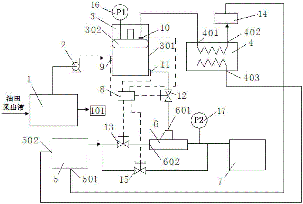
[0073] This embodiment provides a heat energy recovery device for oilfield produced liquid, including: steam separation tank 1, pressure booster pump 2, variable volume separation tank 3, heat exchanger 4, steam boiler 5, ejector 6, heavy oil heater 7. Piston pressure gauge 16, steam pressure gauge 17, associated gas storage tank 14, PLC controller 8, and a check valve 9 electrically connected to the PLC controller 8, the first control valve 10, the second control valve 11, the first Three control valves 12 , a fourth control valve 13 , and a fifth control valve 15 .

[0074] The variable volume separation tank 3 comprises: a tank body 301, a piston 302 arranged in the tank body 301 and a steam pressure gauge 17 arranged on the top of the piston 302, the piston 302 can move axially in the tank body 301, and the tank body 301 is divided into Two upper and lower chambers separated from each other and variable in volume can monitor the internal pressure of the lower chamber throu...

Embodiment 2

[0077] In this embodiment, the oilfield produced fluid heat energy recovery device provided in Example 1 is used to recover the heat energy of the oilfield produced fluid, including the following steps:

[0078] The oilfield production fluid is introduced into the steam separation tank 1 for separation to obtain a gas phase part and a liquid phase part. The liquid phase part is discharged through the sewage discharge port 101 on the steam separation tank 1, while the gas phase part is discharged through the booster pump 2 and the one-way valve 9 flows into the variable volume separation tank 3 for gas-liquid separation, when the value of the piston pressure gauge 16 reaches 3.2-3.5MPa, the water vapor in the variable volume separation tank 3 condenses into a liquid state, and associated gas and condensed water are obtained, making the piston pressure gauge Keep the value of 16 in the range of 3.2-3.5MPa for 10 minutes, then open the first control valve 10 and the second control...


PUM


Abstract

The invention discloses an oilfield produced fluid heat energy recovery device and method, and belongs to the technical field of heat energy recovery. In the device, a volume-variable separation tank comprises a tank body and a piston arranged in the tank body, wherein the piston can axially move in the tank body and divide the tank body into an upper cavity and a lower cavity; a check valve is arranged in the middle of the tank body, a first control valve is arranged at the upper portion of the piston, and a second control valve is arranged at the lower portion of the tank body. The gas phase outlet of a steam separation tank, a pressurizing pump, the check valve and the feed port in the middle of the volume-variable separation tank are sequentially connected; the outlet of the lower portion of the volume-variable separation tank, the second control valve, a third control valve and one inlet of an ejector are sequentially connected; the first control valve, the outlet of the upper portion of the volume-variable separation tank, the associated gas inlet of a heat exchanger and the associated gas outlet of the heat exchanger, the fuel inlet of a steam boiler, a fourth control valve, the other inlet of the ejector, the outlet of the ejector and a thick oil heater are sequentially connected; and the boiler water feed outlet of the heat exchanger is connected with the boiler water feed inlet of the steam boiler.

Description

technical field [0001] The invention relates to the field of heat energy recovery devices, in particular to a heat energy recovery device and method for oilfield production fluid. Background technique [0002] The oilfield production fluid obtained in the process of oilfield exploitation usually has a relatively high temperature, up to 180-220℃, which contains a lot of heat energy. Generally, oilfield production fluid is separated by three-phase separator to obtain oil, oilfield gas, oilfield sewage and associated gas, etc. Among them, the separated associated gas cannot be burned because it is mixed with water vapor. Therefore, the associated gas is directly discharged into the air, which wastes heat energy and oil and gas resources, and causes air pollution. Therefore, it is very necessary to provide a heat energy recovery device for oilfield produced fluid that can efficiently utilize the heat energy of associated gas. [0003] At present, the prior art provides a waste...

Claims


Application Information

Patent Timeline
Patent Type & Authority Applications(China)
IPC IPC(8): E21B43/24B01D1/30F22B33/18F22D1/00
CPCY02P70/10
Inventor 姜一超王鹏举马永伟王子权宗超伦孟笑天孟欢殷新华李建华孟兵川
Owner PETROCHINA CO LTD
Why Eureka
Try Eureka