
Hydrogen flame ionization detector and working method thereof

A hydrogen flame and ionization technology, applied in the direction of instruments, measuring devices, scientific instruments, etc., can solve the problems of increased structural complexity and maintenance costs, poor batch consistency, small parts and many processes, etc., to achieve simple and mature processing technology, simplified The effect of production process and simplified design

Inactive Publication Date: 2016-04-13
WEIFANG UNIVERSITY
View PDF7 Cites 8 Cited by
  • Summary
  • Abstract
  • Description
  • Claims
  • Application Information

AI Technical Summary

Problems solved by technology

The following problems exist in the traditional FID structure scheme: 1. In order to apply the polarization voltage, the polarized pole must be electrically insulated from the ground, that is, the polarized pole is made of metal conductive material, and the nozzle is made of insulating material, and then the polarized pole is combined with the nozzle
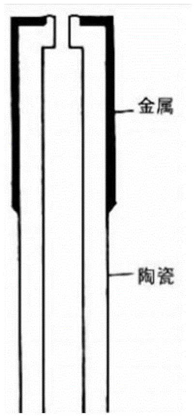
At present, the nozzles are mostly made of ceramics or quartz, and the polarized electrodes and nozzles are mostly combined by brazing. Due to the small parts and many processes, the processing is difficult.
2. The polarized pole is made of metal, mostly circular, and is required to be on the same plane as the nozzle (the polarized pole is lower than the nozzle, the sensitivity decreases, otherwise the noise increases), and the batch consistency is poor
3. The FID has two lead wires, which increases the structural complexity and maintenance cost

Method used


Image

  • Hydrogen flame ionization detector and working method thereof
  • Hydrogen flame ionization detector and working method thereof
  • Hydrogen flame ionization detector and working method thereof

Examples


Embodiment 1

[0021] Such as figure 1 with 3 shown.

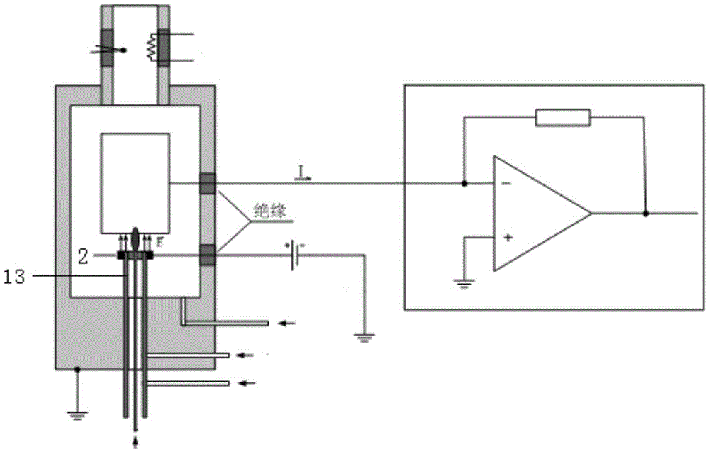
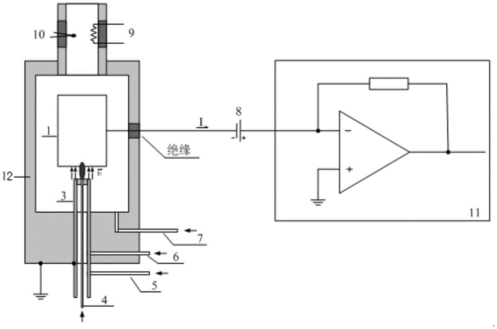
[0022] A hydrogen flame ionization detector, comprising an outer cover 12, a chromatographic column 4, a collecting electrode 1, a polarizing electrode 2, a conductive nozzle 3, and a detection circuit 11; Pole 1 is connected to the negative pole of polarized power supply 8; the conductive nozzle is at 3 ground potential. The hydrogen flame ionization detector of the present invention connects the polarization voltage in series to the signal lead-out line of the collector 1, and at the same time combines the traditional polarizer 2 and the insulating nozzle 13 into one, and keeps them at the ground potential to ensure that the detector While maintaining normal functions, the equipment complexity and production process are simplified.

Embodiment 2

[0024] The difference of the hydrogen flame ionization detector shown in Embodiment 1 is that the conductive nozzle 3 is made of stainless steel. The conductive nozzle 3 is made of stainless steel, which is convenient for precision machining, solves the problem of high processing technology requirements for the insulating nozzle 13 and the polarizing electrode 2, facilitates mass production, and improves production efficiency and production cost.

Embodiment 3

[0026] A kind of working method of hydrogen flame ionization detector as described in embodiment 1-2, comprises steps as follows, the gas that chromatographic column 4 flows out is mixed with make-up gas (nitrogen) and hydrogen earlier, mixes with combustion-supporting gas (air) again Finally, the outlet of the conductive nozzle 3 is ignited by the ignition wire 9 to form a hydrogen flame; the thermal and chemical energy of the flame is used to ionize the organic matter into particles with positive and negative charges; the conductive nozzle 3 maintains the ground potential, and the collector 1 is at a low potential , after the polarizing voltage is applied between the polarizing pole 2 and the collecting pole 1, an electrostatic field E is formed (direction such as image 3 As shown), the charged particles move directionally under the action of the electric field E to form a microcurrent, and the detection circuit 11 amplifies the microcurrent and converts it into a voltage sig...


PUM


Abstract

The invention relates to a hydrogen flame ionization detector and working method thereof. The hydrogen flame ionization detector comprises an outer cover, a chromatographic column, a collector, a polarization electrode, a conductive nozzle and a detection circuit. The collector is connected with the detection circuit after being connected with a polarization power source in series. The collector is connected with the negative pole of the polarization power source. The conductive nozzle is a ground potential. According to the hydrogen flame ionization detector, polarization voltage is connected to a signal outgoing line of the collector in series, meanwhile, the traditional polarization electrode and the nozzle are combined into a whole, the ground potential is kept, the normal function of the detector is ensured, and the equipment complexity and production technology are simplified.

Description

technical field [0001] The invention relates to a hydrogen flame ionization detector and a working method thereof, belonging to the technical field of detection equipment. Background technique [0002] Hydrogen Flame Ionization Detector (FID) is a typical destructive, mass-type detector; the flame generated by the combustion of hydrogen and air is used as the excitation source. When organic compounds enter the flame of hydrogen and oxygen combustion, chemical Ionization, ionization produces ions that are several orders of magnitude higher than the base flow, and under the directional action of a high-voltage electric field, an ion flow is formed, and a weak ion flow (10 -12 ~10 -8 A) After a high impedance (10 6 ~10 11 Ω) amplifier to amplify and become an electrical signal proportional to the amount of organic compounds entering the flame, so the organic compounds can be quantitatively analyzed according to the signal size. Its main feature is that it responds to almost...

Claims


Application Information

Patent Timeline
Patent Type & Authority Applications(China)
IPC IPC(8): G01N30/68
CPCG01N30/68
Inventor 马海斌王林同张运臣张彭
Owner WEIFANG UNIVERSITY
Learn More