Device for measuring resistivity and seebeck coefficient and usage method

A technique for measuring Seebeck coefficient and measuring resistance, which is applied in measuring devices, measuring resistance/reactance/impedance, and measuring electrical variables, etc. It can solve the problems of objective evaluation affecting product performance, low measurement accuracy, and poor repeatability of measurement results.

Active Publication Date: 2016-04-13
湖北赛格瑞新能源科技有限公司
View PDF7 Cites 8 Cited by
  • Summary
  • Abstract
  • Description
  • Claims
  • Application Information

AI Technical Summary

Problems solved by technology

However, for the measuring devices of resistivity and Seebeck coefficient of larger samples used by domestic manufacturers, the resistivity measurement is mostly based on the two-probe method, and the Seebeck coefficient is mostly measured using the static method, which has low measurement accuracy and repeated measurement results. Poor performance, unable to accurately measure the resistivity and Seebeck coefficient of different micro-regions, which affects the objective evaluation of product performance

Method used


Image

  • Device for measuring resistivity and seebeck coefficient and usage method
  • Device for measuring resistivity and seebeck coefficient and usage method
  • Device for measuring resistivity and seebeck coefficient and usage method

Examples


Embodiment 1

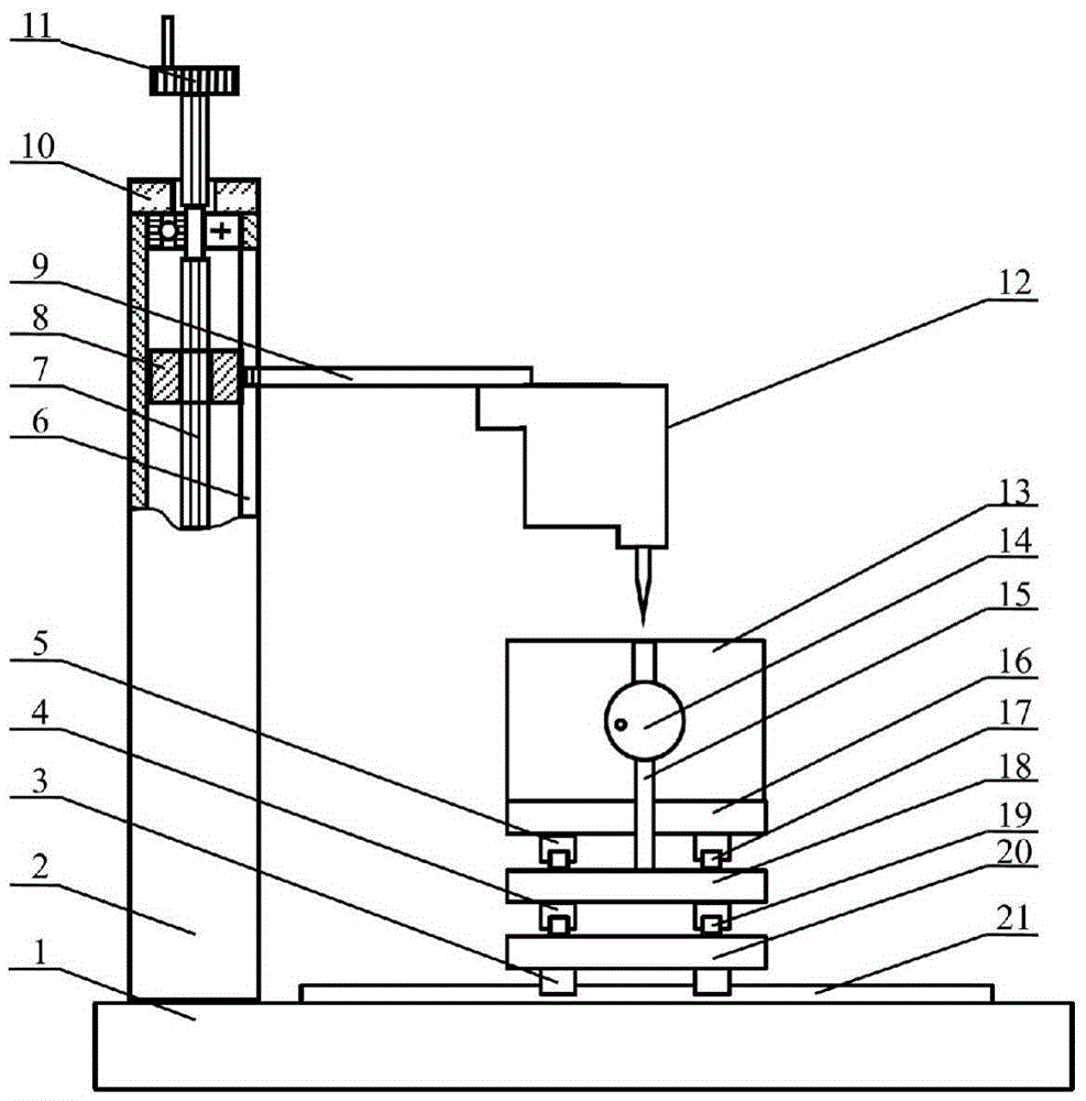
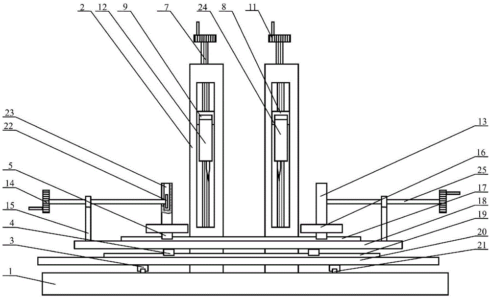
[0063] A device for measuring resistivity and Seebeck coefficient. Such as figure 1 with figure 2 As shown, the device consists of a lifting system, a horizontal moving system and a measuring system. For the convenience of description, this embodiment uses figure 2 the left side of is the left side, figure 1 The left side is the rear side.

[0064] The structure of the lifting system is as follows: Figure 1 ~ Figure 4 Shown:

[0065] Such as figure 1 with figure 2 Shown: two square steel pipes 2 are symmetrically fixed on the rear side of the upper surface of base plate 1, and lower bearing, nut type slide block 8, upper bearing and end cover 10 are successively housed in square steel pipe 2 from bottom to top. The lower end of vertical screw mandrel 7 is installed in the lower bearing, and the middle part of vertical screw mandrel 7 is threadedly connected with nut type slide block 8, and the upper end of vertical screw mandrel 7 passes through upper bearing and e...

Embodiment 2

[0110] A device for measuring resistivity and Seebeck coefficient. The device described in this embodiment is the same as that in Embodiment 1.

[0111] Method for measuring resistivity and Seebeck coefficient using the device.

[0112] The sample 36 to be tested in this embodiment is N-type Bi 2 Te 2.7 Se 0.3 Sample, the sample to be tested 36 is a cross-sectional size of 20 × 20mm 2 and a cuboid with a longitudinal dimension of 100mm.

[0113] The measuring method of resistivity described in the present embodiment is:

[0114] Step 1.1, such as Figure 7 As shown, first a surface to be tested of the sample to be tested 36 is divided into 10 regions to be tested; then the surface to be tested of the sample to be tested 36 is placed upwards, placed between the clamping electrodes 13 along the longitudinal direction, and rotated Move the lower hand wheels 14 on both sides to clamp the sample 36 to be tested.

[0115] Step 1.2 to step 1.4 are the same as step 1.2 to step...

Embodiment 3

[0145] A device for measuring resistivity and Seebeck coefficient. The device described in this embodiment is the same as that in Embodiment 1.

[0146] Method for measuring resistivity and Seebeck coefficient using the device.

[0147] The sample 36 to be tested in this embodiment is P-type Bi 0.5 Sb 1.5 Te 3 A test piece, which is a cylinder with a diameter of 40 mm and a longitudinal dimension of 400 mm.

[0148] The measuring method of resistivity described in the present embodiment is:

[0149] Step 1.1, such as Figure 8 As shown, first a surface to be tested of the sample to be tested 36 is divided into 20 regions to be tested; then the surface to be tested of the sample to be tested 36 faces up, and is placed between the clamping electrodes 13 along the longitudinal direction, and rotated Move the lower hand wheels 14 on both sides to clamp the sample 36 to be tested.

[0150] Step 1.2 to step 1.4 are the same as step 1.2 to step 1.4 in Example 1.

[0151] Step...


PUM

PropertyMeasurementUnit
lengthaaaaaaaaaa
sizeaaaaaaaaaa

Abstract

The invention relates to a device for measuring resistivity and seebeck coefficient and a usage method. The technical scheme is characterized in that: the device consists of an elevation system, a horizontal movement system and a measurement system. A hot end electrode (12) and a cold end electrode (24) are respectively fixed on one end of a horizontal rod (9); the other end of the horizontal rod (9) is connected to a vertical screw rod (7) through a screw nut type sliding block; during the measurement, the clamping electrode (13) horizontally moves a test sample (36) to a position right under the hot end telescopic electric level probe (29) and a cold end telescopic electric level probe (30) through the two sliding blocks which are perpendicular to each other in two moving directions; the voltage, the current and the temperature of various areas to be detected can be read through a high precision digital voltage gauge (34), a high precision digital current gauge (38), a first temperature gauge (35) and a second temperature gauge (37); and the corresponding resistivity and the seebeck coefficient are obtained through calculation. The invention can realize the direct measurement of the resistivity and the seebeck coefficient of the cuboid sample and the circular column sample in various areas, and the measurement accuracy is high.

Description

technical field [0001] The invention belongs to the technical field of semiconductor material measurement. In particular, it relates to a device for measuring resistivity and Seebeck coefficient and its application method. Background technique [0002] Resistivity and Seebeck coefficient are important parameters of semiconductor materials. They can not only characterize the electrical transport performance of the material, but also indirectly reflect the carrier concentration and mobility inside the material. Due to the different conduction mechanisms of semiconductor materials and metal materials, it is impossible to directly measure their resistivity using an ohmmeter based on the two-probe method. When the measuring electrode of the ohmmeter is in contact with the semiconductor, the contact resistance effect and the minority carrier injection phenomenon will appear, causing the measured resistivity value of the semiconductor material to deviate greatly from the true val...

Claims


Application Information

Patent Timeline
Patent Type & Authority Applications(China)
IPC IPC(8): G01R27/02G01N25/20
CPCG01N25/20G01R27/02
Inventor 樊希安荣振洲江程鹏张城诚李光强
Owner 湖北赛格瑞新能源科技有限公司
Why Eureka
Try Eureka