An integrated high-power fiber laser output system with cladding light filtering function

A fiber laser and output system technology, applied in multi-layer core/cladding fibers, cladding fibers, lasers, etc., can solve the problems of inability to handle cladding pump light, inability to solve the return light intensity, inability to concentrate output, etc. , to achieve the effect of compact and practical structure, simple structure and convenient production

Active Publication Date: 2018-11-30
NAT UNIV OF DEFENSE TECH
View PDF6 Cites 0 Cited by
  • Summary
  • Abstract
  • Description
  • Claims
  • Application Information

AI Technical Summary

Problems solved by technology

However, this scheme also has an important defect, that is, it can only transmit the signal light in the fiber core but cannot deal with the pump light in the cladding.
Taking the cladding pump light in the double-clad fiber pumping technology as an example, on the one hand, due to the large numerical aperture (NA) of the cladding pump light, it diverges rapidly to the surroundings during the transmission process and cannot be output in a concentrated manner; On the one hand, due to the difference in wavelength between the pump light and the signal light, the anti-reflection coating fails to solve the problem of the return light intensity, which will bring a lot of heat accumulation

Method used


Image

  • An integrated high-power fiber laser output system with cladding light filtering function
  • An integrated high-power fiber laser output system with cladding light filtering function
  • An integrated high-power fiber laser output system with cladding light filtering function

Examples


Embodiment Construction

[0024] The present invention will be further described in detail below in conjunction with the accompanying drawings and specific embodiments.

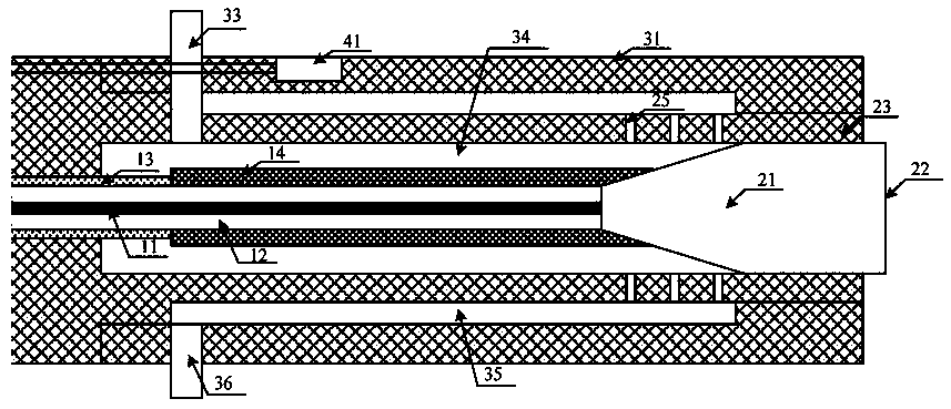
[0025] Such as figure 2 As shown, the integrated high-power fiber laser output system with cladding light filtering function of the present invention includes optical fiber, cladding light filtering assembly, glass fiber end cap and packaging assembly and water cooling circulation assembly, glass fiber end cap and The packaging assembly includes a glass fiber end cap 21 and a packaging fixture 23, and one end of the glass fiber end cap and the packaging assembly forms an output surface 22; the cladding light filtering assembly, the glass fiber end cap and the packaging assembly are all located in the water cooling cycle assembly; The optical fiber core 11 and the glass optical fiber end cap 21 are welded and packaged in the packaging fixture 23; the cladding light filtering component is a high refraction glue layer 14 located in the ...


PUM


Abstract

The invention discloses an integrated high-power optical fiber laser output system with a cladding light filtering function. The integrated high-power optical fiber laser output system comprises an optical fiber, a cladding light filtering component, a glass optical fiber end cap and packaging component and a water cooling circulation component. The glass optical fiber end cap and packaging component comprises a glass optical fiber end cap and a packaging clamp. The cladding light filtering component and the glass optical fiber end cap and packaging component are arranged in the water cooling circulation component. The optical fiber core of the optical fiber and the glass optical fiber end cap are welded through fusion and packaged in the packaging clamp. The cladding light filtering component is a high refraction glue layer arranged in the bare optical fiber area on one end of the optical fiber core. The high refraction glue layer converts pumping light in an optical fiber cladding into heat accumulation in the high refraction glue layer by utilizing the refraction effect and performs cooling via the water cooling circulation component. The integrated high-power optical fiber laser output system with the cladding light filtering function has advantages of being simple and compact in structure and convenient to manufacture so that bearable output power can be enhanced and reliability and safety can be enhanced.

Description

technical field [0001] The invention mainly relates to the fields of fiber lasers and fiber amplifiers, in particular to an integrated high-power fiber laser output system with cladding light filtering function. Background technique [0002] Fiber lasers have the advantages of high conversion efficiency, good beam quality, compact structure, easy heat dissipation, and good working stability. They have been widely used in many fields such as industrial processing, biomedicine, and national defense. In recent years, with the maturity of double-clad fiber pumping technology and the improvement of fiber manufacturing process, the output power of fiber laser has been continuously improved, and the output power of single-mode fiber laser has exceeded 10KW. With the improvement of the output power of fiber lasers, the laser output method is also facing great challenges. One of the most important problems is the optical damage and thermal load of the output end face. Since the lase...

Claims


Application Information

Patent Timeline
Patent Type & Authority Patents(China)
IPC IPC(8): H01S3/067H01S3/042G02B6/036
CPCG02B6/036H01S3/0407H01S3/042H01S3/06708
Inventor 许晓军周旋风陈子伦王泽锋侯静张斌陈胜平
Owner NAT UNIV OF DEFENSE TECH
Why Eureka
Try Eureka