Super-continuum spectrum optical fiber laser output apparatus and laser system

An output device and fiber laser technology, which is applied in the field of laser optoelectronics, can solve the problems of excessive power density, thermal damage, and damage on the output end face of the fiber, and achieve the effect of reducing the optical power density, high power, and increasing the end face damage threshold.

Inactive Publication Date: 2016-04-13
BEIJING UNIV OF TECH
View PDF3 Cites 4 Cited by
  • Summary
  • Abstract
  • Description
  • Claims
  • Application Information

AI Technical Summary

Problems solved by technology

[0003] General fiber laser output devices are only designed for a single wavelength, while the output spectrum of supercontinuum fiber lasers covers the ultraviolet to infrared bands, so the existing fiber laser output devices cannot meet the application requirements of supercontinuum laser output
Secondly, when the laser is working under high power conditions, the output end face of the fiber is prone to thermal damage due to excessive power density.
Finally, the reflected light caused by the surface of the output end and the working surface of the laser will also cause damage to the transmission fiber and other fiber optic components in the fiber laser, making the laser unable to work normally and stably
In addition, under different working conditions of the laser, the return light power caused by the outside world is different. If the real-time monitoring and early warning of the laser return light power is not carried out, it may cause permanent damage to the laser.

Method used


Image

  • Super-continuum spectrum optical fiber laser output apparatus and laser system
  • Super-continuum spectrum optical fiber laser output apparatus and laser system
  • Super-continuum spectrum optical fiber laser output apparatus and laser system

Examples


Embodiment Construction

[0018] The specific implementation manners of the present invention will be further described below in conjunction with the drawings and examples. The following examples are only used to illustrate the technical solution of the present invention more clearly, but not to limit the protection scope of the present invention.

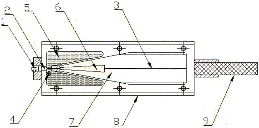
[0019] figure 1 A schematic structural view of the supercontinuum fiber laser output device of the present invention is shown.

[0020] refer to figure 1 , the supercontinuum fiber laser output device of an embodiment of the present invention, specifically includes:

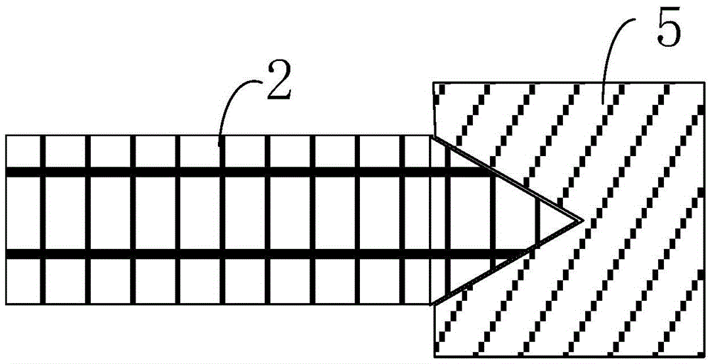
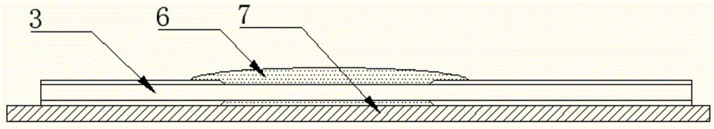
[0021] Laser transmission module, return light processor 5, light stripper 6, heat processor 7 and package module 8, wherein, laser transmission module comprises the transmission optical fiber 3, output end cap 2 and beam focusing and collimating part 1 connected in sequence, and setting A photodetector 4 on the side of the output end cap close to the transmission fiber.

[0022] like fig...


PUM


Abstract

The invention provides a super-continuum spectrum optical fiber laser output apparatus and a laser system. The output apparatus comprises a laser transmission module, a returned-light processor, an optical stripper, a thermal processor and a packaging module; the laser transmission module comprises transmission optical fibers, an output end cap and a light beam focusing collimation part that are connected in sequence, and a photoelectric detector arranged on one side, close to the transmission optical fibers, of the output end cap; the photoelectric detector is used for monitoring the returned-light power at the output end of the output end cap; the returned-light processor is arranged on one side, connected with the transmission optical fibers, of the output end cap; the optical stripper is arranged on the transmission optical fibers close to the output end cap; the thermal process is arranged below the laser transmission module; and the packaging module is used for packaging the laser transmission module, the returned-light processor, the optical stripper and the thermal processor. According to the super-continuum spectrum optical fiber laser output apparatus, high-power and broadband spectrum stable laser output can be realized by performing special treatment on the output end of the whole apparatus, and by performing prompt processing on the returned light and thermal accumulation.

Description

technical field [0001] The invention relates to the technical field of laser optoelectronics, in particular to a high-power supercontinuum optical fiber laser output device and a laser system. Background technique [0002] High-power supercontinuum fiber optic light source is a new type of laser light source with an ultra-wide spectral range. Compared with traditional broadband light sources (such as incandescent lamps, ASE light sources, and SLED light sources), it has a wider spectral range and better coherence characteristics. etc., so it has important applications in many fields. Such as laser radar, long-distance communication, medical imaging, spectral analysis and optical metrology. In recent years, with the continuous development of supercontinuum generation technology, the output power level of supercontinuum fiber laser has risen from the initial watt level to tens of watts or even hundreds of watts, which makes the output of supercontinuum fiber laser The requir...

Claims


Application Information

Patent Timeline
Patent Type & Authority Applications(China)
IPC IPC(8): H01S3/13
CPCH01S3/13
Inventor 葛廷武孙畅王智勇李思源符聪安娜赵小涵丁星
Owner BEIJING UNIV OF TECH
Why Eureka
Try Eureka