Cylinder type tooth plate coal crushing gangue machine

A cylinder type and tooth plate technology is applied in the field of the cylinder type tooth plate coal crusher and gangue discharger to achieve the effects of eliminating gangue with less coal, small external dimensions and less investment.

Active Publication Date: 2018-06-26
张路征
View PDF8 Cites 0 Cited by
  • Summary
  • Abstract
  • Description
  • Claims
  • Application Information

AI Technical Summary

Problems solved by technology

[0004] The purpose of the present invention is to solve the shortcomings of manual gangue picking and drum-type selective crushers, and provide a cylinder-type tooth plate coal-breaking and gangue-discharging machine that can selectively remove large chunks of coal gangue

Method used


Image

  • Cylinder type tooth plate coal crushing gangue machine
  • Cylinder type tooth plate coal crushing gangue machine

Examples


Embodiment 1

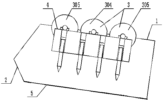
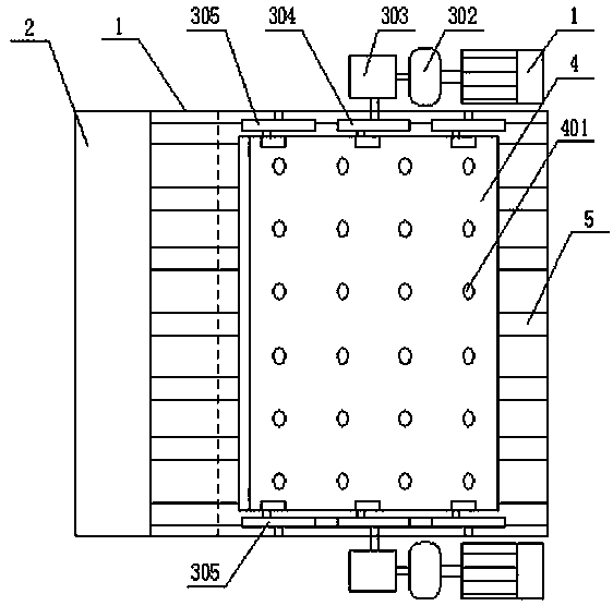
[0019] The cylinder type tooth plate coal breaking and gangue discharge machine includes a box body 1, the left end of the box body 1 is provided with an inclined feeding chute 2, the bottom of the box body 1 is fixed with a sieve plate 5, and the sieve plate 5 is connected to the bottom edge of the feeding chute 2 connect. The upper part of the sieve plate 5 is provided with a cylinder tooth plate 4 and a driving device 3 which can allow the cylinder tooth plate 4 to perform circular motion. Such as figure 2 As shown, a motor is provided on both sides of the cylinder tooth plate 4 to drive the driving eccentric 304 after passing through the hydraulic coupling 302 and the reducer 303 . The two active eccentric wheels 304 drive the four passive eccentric wheels 305, so that the cylinder tooth plate 4 keeps parallel and performs circular motion as a whole, and the radius of the circular motion is 400 mm. Said cylinder gear plate 4 is evenly distributed with piston cylinders 4...

Embodiment 2

[0022] Such as figure 1 As shown, on the basis of Example 1, the angle between the sieve plate 5 and the horizontal plane is set to 20°, and the angle between the feeding chute 2 and the horizontal plane is 50°. When the chute 2 enters the box body 1, it is convenient to feed the material, which reduces the resistance when the piston rod picks up the material, and at the same time, the material will not automatically slide down from the sieve plate 5 . Simultaneously, the mechanical driving mode of the present invention can be changed into hydraulic pressure or air pressure. According to the amount of material and the flow rate of the material, the piston cylinder 401 on the cylinder tooth plate 4 can also be adjusted to six horizontal rows, six vertical rows, and the spacing between the horizontal and vertical rows. The present invention can adjust the structure of the present invention according to different factors in the actual operation process, such as the difference of...


PUM


Abstract

A cylinder-type toothed plate machine for coal breaking and gangue removal, comprising a tank (1). An oblique feeding chute (2) is arranged at the left end of the tank, screen plates (5) connected to the edge of the bottom of the feeding chute are fixed to the bottom of the tank, a cylinder toothed plate (4) and driving devices (3) capable of allowing the cylinder toothed plate to conduct a circumferential motion are arranged on the upper portion of the screen plates, piston-type cylinders (401) arranged in rows transversely and in lines vertically are evenly distributed on the cylinder toothed plate, and piston rods (403) of the piston-type cylinders are disposed perpendicular to the surface of the screen plates and can move up and down in the cylinders. The screen plates are evenly arranged perpendicular to the edge of the bottom of the feeding chute to form uniform screen seams, the screen plates are located in a middle position below two transverse rows of piston-type cylinders, and each transverse row of piston rods directly faces one screen seam. The cylinder-type toothed plate machine for coal breaking and gangue removal can selectively remove bulky gangue and has the advantages of being adjustable in breaking hardness, less coal being carried in removed gangue, and no need of human attendance, as well as small external dimensions, an easy arrangement, and being firm and durable, etc.

Description

technical field [0001] The invention relates to coal preparation equipment for coal mines, in particular to a cylinder-type tooth-plate coal-breaking and gangue-discharging machine. Background technique [0002] With the development of the coal industry, the geological conditions of coal seams in many coal mines have deteriorated, the number of geological structures has increased, and the wide application of top-coal caving technology has led to a significant increase in the proportion of bulk materials in raw coal. [0003] Moving sieve jig machine, shallow groove dense medium separator and ray method single-grain coal-gangue separation system, the upper limit of the separation particle size is 300mm, powerless for +300mm coal gangue; +300mm coal gangue, the separation means only There are artificial hand selection and drum type selective crusher. Due to the large size of the drum-type selective crusher, the high cost of infrastructure, the large amount of maintenance, and...

Claims


Application Information

Patent Timeline
Patent Type & Authority Patents(China)
IPC IPC(8): B02C1/12B02C23/16
CPCB02C1/12
Inventor 张路征
Owner 张路征
Why Eureka
Try Eureka