Alumina continuous feeding device

An alumina and feeding tube technology, applied in the field of aluminum electrolysis, can solve the problems of low current efficiency, poor stability of aluminum electrolytic cells, increased energy consumption, etc., and achieve the effects of improving current efficiency, reducing furnace bottom sedimentation, and reducing effect coefficients

Active Publication Date: 2018-03-06
SNTO TECH GRP
View PDF9 Cites 1 Cited by
  • Summary
  • Abstract
  • Description
  • Claims
  • Application Information

AI Technical Summary

Problems solved by technology

[0004] Since the feeding method of the alumina point-type feeding device is intermittent feeding, the concentration of alumina fluctuates significantly, the concentration before feeding is low, the concentration after feeding is high, and the heat balance of the tank fluctuates greatly, which affects the stability and stability of the aluminum electrolytic cell. Current efficiency; a large amount of alumina is fed into a single batch of point feeding method, but the current low superheat process makes the dissolution process of alumina more difficult, and the undissolved alumina sinks into the aluminum liquid, which causes the aluminum liquid below the feeding port A large amount of alumina precipitates accumulate in the layer, and the precipitate covers the bottom of the furnace with the flow of aluminum liquid, resulting in an increase in the pressure drop at the bottom of the furnace and increased energy consumption. A large amount of alumina is easy to collide with the shelling device after accelerating on the inclined wall, causing part of the alumina to scatter on the cell cover of the aluminum electrolytic cell, and the actual reduction of the input material will easily cause the anode effect, destroy the thermal balance of the aluminum electrolytic cell, and increase energy consumption
Therefore, the aluminum oxide point-type feeding device of the related art has the disadvantages of large fluctuations in the thermal balance of the aluminum electrolytic cell after feeding, poor stability of the aluminum electrolytic cell, low current efficiency, and high energy consumption.

Method used


Image

  • Alumina continuous feeding device
  • Alumina continuous feeding device
  • Alumina continuous feeding device

Examples


Embodiment 1

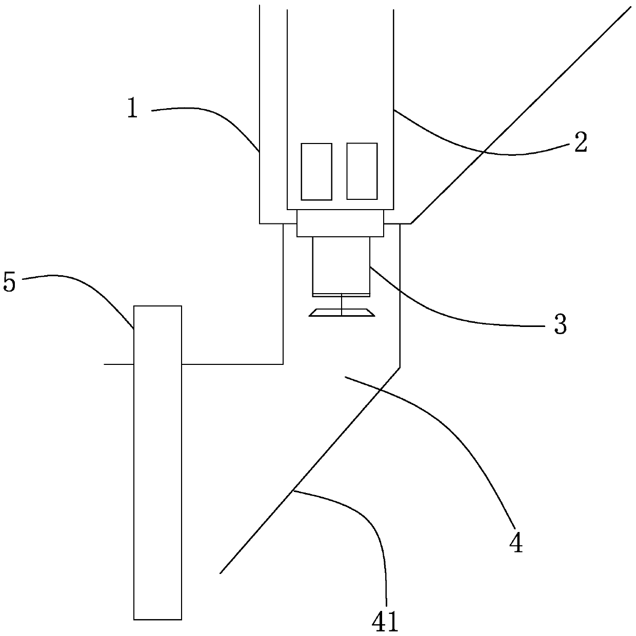
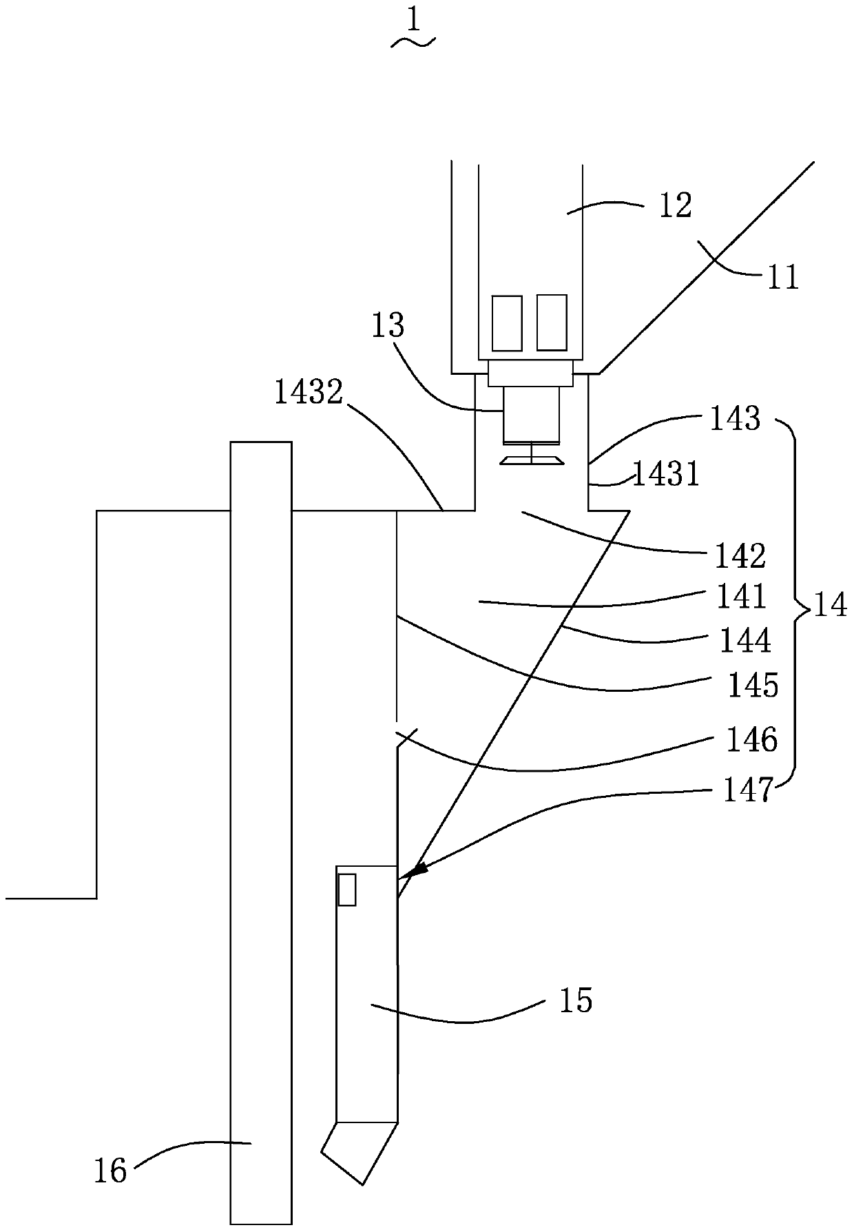
[0032] see figure 2 , is a schematic structural view of Embodiment 1 of the alumina continuous feeding device of the present invention. The alumina continuous feeding device 1 includes an alumina bin 11 , a feeding cylinder 12 , a fixed container 13 , a feeding channel 14 , a feeding pipe 15 and a shelling device 16 . The feeding cylinder 12 is arranged in the alumina material box 11 , and the fixed container 13 is connected to the bottom of the feeding cylinder 12 and is located in the feeding channel 14 . The shell breaking device 16 is located directly above the feed port (not shown) of the aluminum electrolytic cell, and is set opposite to the discharge channel 14 at intervals. The alumina material enters the feeding channel 14 through the fixed container 13, and then enters the aluminum electrolytic cell through the feeding pipe 15.

[0033] The feeding passage 14 includes a receiving space 141 , a feeding opening 142 , a connecting portion 143 , an inclined portion 14...

Embodiment 2

[0044] see Figure 6 , is a schematic structural view of Embodiment 2 of the alumina continuous feeding device of the present invention. The alumina continuous feeding device 2 includes an alumina bin 21 , a feeding cylinder 22 , a fixed container 23 , a feeding channel 24 , a feeding pipe 25 and a shelling device 26 . The structure and positional relationship of the alumina material box 21, the feeding cylinder 22, the fixed container 23 and the shelling device 26 are the same as those in the first embodiment.

[0045] The feeding passage 24 includes a receiving space 241 , a feeding opening 242 , a connecting portion 243 , an inclined portion 244 , a blocking portion 245 , an overflow opening 246 , a feeding opening 247 and a funnel device 248 . The fixed container 23 is accommodated in the accommodating space 241, and the structure and positional relationship of the material inlet 242, the connecting portion 243, the inclined portion 244, the blocking portion 245, the over...

Embodiment 3

[0052] see Figure 8 , is a schematic structural view of Embodiment 3 of the alumina continuous feeding device of the present invention. The alumina continuous feeding device 3 includes an alumina bin 31 , a feeding cylinder 32 , a fixed container 33 , a feeding channel 34 , a feeding pipe 35 and a shelling device 36 . The positional relationship of the alumina material box 31 , the feeding cylinder 32 , the constant container 33 and the shelling device 36 is the same as that of the first embodiment.

[0053] The discharge channel 34 includes a receiving space 341 , a connecting portion 342 , an inclined portion 343 , a blocking portion 344 , an overflow port 345 and a funnel device 346 , and the positional relationship of each component is the same as that of the second embodiment.

[0054] In this embodiment, the connection part 342 includes a first connection part 3421 and a second connection part 3422, the structure and location of which are the same as those in the first...


PUM

PropertyMeasurementUnit
diameteraaaaaaaaaa

Abstract

The invention provides a continuous aluminum oxide blanking device. The continuous aluminum oxide blanking device comprises an aluminum oxide material bin, a blanking channel, a constant volume device, a blanking tube and a crust breaking device, wherein the blanking channel is connected with the bottom of the aluminum oxide material bin and provided with a containing space, the constant volume device is contained in the containing space and communicated with the bottom of the aluminum oxide material bin, the crust breaking device is opposite to the blanking tube and the blanking channel in a spaced mode, the blanking tube comprises a feeding opening formed in the top of the blanking tube and a discharging opening formed in the bottom of the blanking tube, and the feeding opening is communicated with the bottom of the blanking channel. Compared with the prior art, according to the continuous aluminum oxide blanking device, intermittent blanking is changed into continuous blanking, aluminum oxide passes through the blanking channel and then slowly enters the blanking tube, blanking is conducted stably, fluctuation of the temperature of an electrolytic tank and the concentration of the aluminum oxide is reduced, electric current efficiency is further improved, and energy consumption is lowered.

Description

technical field [0001] The invention relates to the technical field of aluminum electrolysis, in particular to an alumina continuous feeding device. Background technique [0002] With the increase of the capacity of modern aluminum electrolytic cells, and the low pole distance technology implemented by the aluminum industry in pursuit of energy saving of aluminum electrolytic cells, some aluminum factories have adopted the method of weakening the melt in the tank to resist the fluctuation of the aluminum liquid in the tank. The flow design makes it more and more difficult for the alumina added to the electrolyte to be transported and dispersed in the tank after the current quasi-continuous feeding method based on point feeding. [0003] see figure 1 , is a schematic structural diagram of an alumina blanking device in the prior art. The alumina point blanking device uses a timing constant volume blanking device for intermittent blanking. The alumina point-type feeding devic...

Claims


Application Information

Patent Timeline
Patent Type & Authority Patents(China)
IPC IPC(8): C25C3/14
CPCC25C3/14
Inventor 章宣洪波敬叶灵李泉毛凯萍
Owner SNTO TECH GRP
Why Eureka
Try Eureka