
Flue gas desulfurization and denitrification optimization control method based on hysteresis model

A desulfurization, denitrification and optimal control technology, applied in the field of desulfurization and denitrification, can solve the problems of increasing the amount of ammonia sprayed, the concentration of nitrogen oxides at the outlet exceeding the standard, and it is difficult to control the spraying amount of limestone slurry, so as to achieve the effect of improving precision and accuracy.

Pending Publication Date: 2022-03-25
STATE GRID HEBEI ENERGY TECH SERVICE CO LTD +2
View PDF0 Cites 1 Cited by
  • Summary
  • Abstract
  • Description
  • Claims
  • Application Information

AI Technical Summary

Problems solved by technology

The State Council also proposed to strengthen the emission reduction of pollutants and continue to promote the desulfurization and denitrification work plan of the power industry, requiring new coal-fired units to fully implement desulfurization and denitrification to achieve emission standards, and existing coal-fired units that have not yet installed desulfurization and denitrification facilities must be equipped with flue gas Desulfurization and denitrification facilities, units that cannot stably meet the emission standards shall be transformed
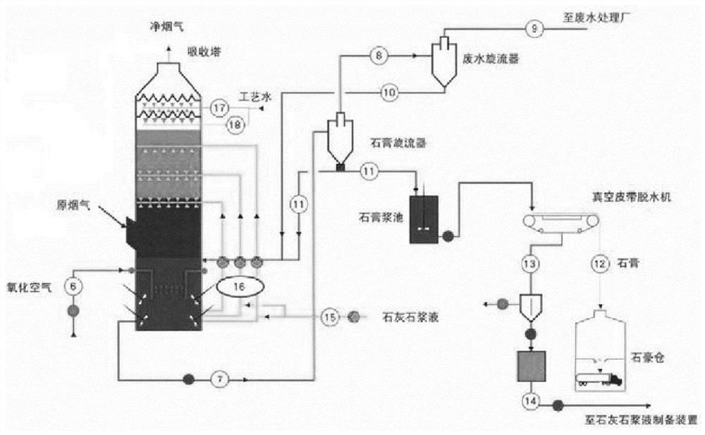
[0003] The common process of desulfurization system is limestone-gypsum wet flue gas desulfurization. The whole process mainly includes absorption tower system, limestone slurry preparation system and gypsum dehydration treatment system. The absorption tower has two outlets, one for gypsum slurry outlet, real-time detection PH value, that is, to detect the pH value of the gypsum slurry outlet; the other outlet is the clean flue gas outlet, to detect the concentration of the carbon dioxide building, that is, to detect the concentration of sulfur dioxide at the clean flue gas outlet; however, the flue gas reaction of the absorption tower is a large lag, slow It is a dynamic process, and the desulfurization system is a complex control system. The conventional PID control strategy sets the pH value or adjusts the slurry spray volume based on experience. It is difficult to accurately control the limestone slurry spray volume, and it is difficult to effectively control the slurry pH value and Ensure that the value is within the valid range
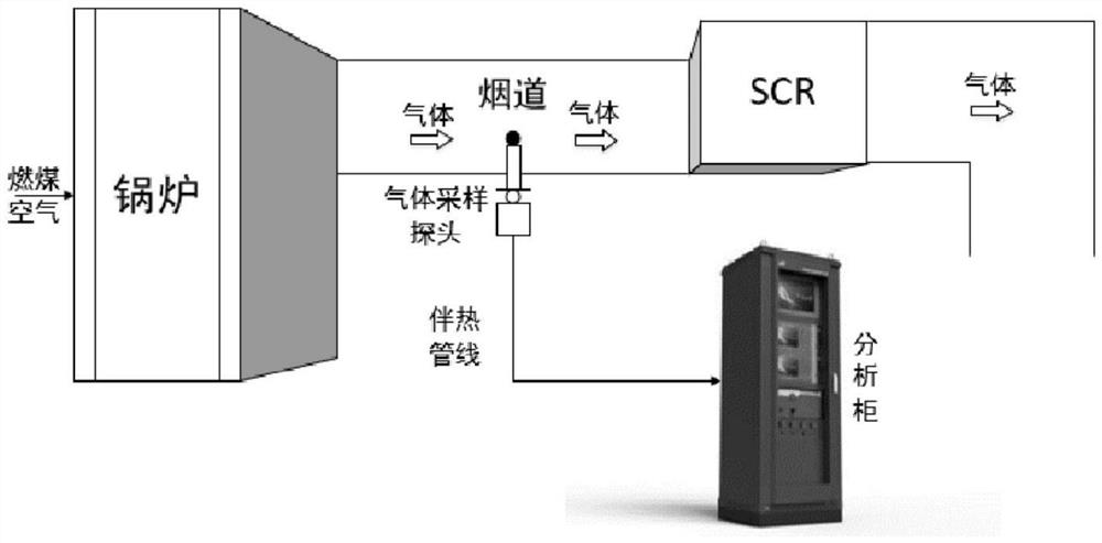
[0004] The common process of denitrification system is SCR denitrification. The main influencing factor is the amount of ammonia water. Too little ammonia water will lead to incomplete reaction, causing the concentration of nitrogen oxides at the outlet to exceed the standard. If the amount of ammonia water is too large, the unreacted ammonia water will be discharged from the system along with the flue gas. , causing air pollution and downstream equipment blockage; the efficient and stable operation of the denitrification system is the key to achieving the emission concentration of nitrogen oxides in the flue gas of the power plant. Due to the characteristics of the denitrification system such as nonlinearity and hysteresis, it is difficult for the traditional PID control technology to maintain the outlet of the denitrification system. The concentration of nitrogen oxides is stable, resulting in excessive fluctuations in the concentration of nitrogen oxides at the outlet. On the one hand, the concentration of nitrogen oxides at the outlet frequently exceeds the standard. The cost of ammonia injection in the denitrification system increases accordingly

Method used


Image

  • Flue gas desulfurization and denitrification optimization control method based on hysteresis model
  • Flue gas desulfurization and denitrification optimization control method based on hysteresis model
  • Flue gas desulfurization and denitrification optimization control method based on hysteresis model

Examples


Embodiment Construction

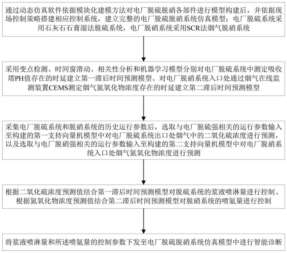
[0075] Such as figure 1 As shown, this embodiment 1 provides an optimal control method for flue gas desulfurization and denitrification based on a hysteresis model, and the optimal control method for flue gas desulfurization and denitrification includes:

[0076] After the dynamic simulation software is used to model the desulfurization and denitrification components of the power plant based on the modular modeling method, and the corresponding control system is built according to the on-site control strategy, a complete simulation model of the desulfurization and denitrification system of the power plant is established; the desulfurization system of the power plant uses limestone-gypsum Wet desulfurization system, the denitrification system of the power plant adopts the SCR method flue gas denitrification system;

[0077] Using change point detection, time window sliding, correlation analysis and machine learning model to establish the first lag time prediction model for the ...


PUM


Abstract

The invention relates to a hysteresis model-based flue gas desulfurization and denitrification optimization control method, which comprises the following steps of: establishing a power plant desulfurization and denitrification system simulation model through dynamic simulation software according to modular modeling and a control strategy; establishing a first delay time prediction model for the time delay existing in the determination of the pH value of an absorption tower in the desulfurization system, and establishing a second delay time prediction model for the time delay existing in the determination of the concentration of flue gas nitrogen oxide at the inlet of the denitration system through a flue gas online monitoring device CEMS; predicting the concentration of sulfur dioxide at a desulfurization outlet and the concentration of nitrogen oxide at a denitration inlet by adopting a support vector machine model; controlling the slurry spraying amount according to the predicted value of the sulfur dioxide concentration in combination with a first lag time prediction model, and controlling the ammonia spraying amount according to the predicted value of the nitrogen oxide concentration in combination with a second lag time prediction model; and the control parameters are issued to the desulfurization and denitrification system simulation model for intelligent diagnosis.

Description

technical field [0001] The invention belongs to the technical field of desulfurization and denitrification, and in particular relates to an optimal control method for flue gas desulfurization and denitrification based on a hysteresis model. Background technique [0002] With the rapid development of various industries, the resulting air pollution has become more and more serious. The emissions of sulfur dioxide and nitrogen oxides have remained high, resulting in serious air pollution and acid rain. Thermal power plants are One of the main sources of sulfur dioxide and nitrogen oxide emissions, so it is imminent to control the emissions of sulfur dioxide and nitrogen oxides from power plants. The State Council also proposed to strengthen the emission reduction of pollutants and continue to promote the desulfurization and denitrification work plan of the power industry, requiring new coal-fired units to fully implement desulfurization and denitrification to achieve emission s...

Claims


Application Information

Patent Timeline
Patent Type & Authority Applications(China)
IPC IPC(8): B01D53/34B01D53/50B01D53/78B01D53/56B01D53/90
CPCB01D53/346B01D53/78B01D53/502B01D53/90B01D53/8625
Inventor 殷喆金飞袁晓磊杨春来李剑锋曹颖赵志军包建东
Owner STATE GRID HEBEI ENERGY TECH SERVICE CO LTD
Learn More