Environmental-protection and energy-conservation treatment technology of sintering flue gas

A technology for sintering flue gas and treatment process, applied in gas treatment, waste heat treatment, air quality improvement and other directions, can solve the problems of single function, large land occupation, construction and operation cost, site occupation waste, etc., to improve economic benefits and reduce The effect of investment and operating costs

Active Publication Date: 2016-04-20
安庆沐尔环保科技有限公司
View PDF5 Cites 27 Cited by
  • Summary
  • Abstract
  • Description
  • Claims
  • Application Information

AI Technical Summary

Problems solved by technology

[0005] To sum up, the current control and removal methods of sintering flue gas pollutants are mostly terminal treatment processes with a single function. With the increase of pollutant emission restrictions, the terminal treatment process facilities can only be more and mo

Method used


Image

  • Environmental-protection and energy-conservation treatment technology of sintering flue gas

Examples


Embodiment

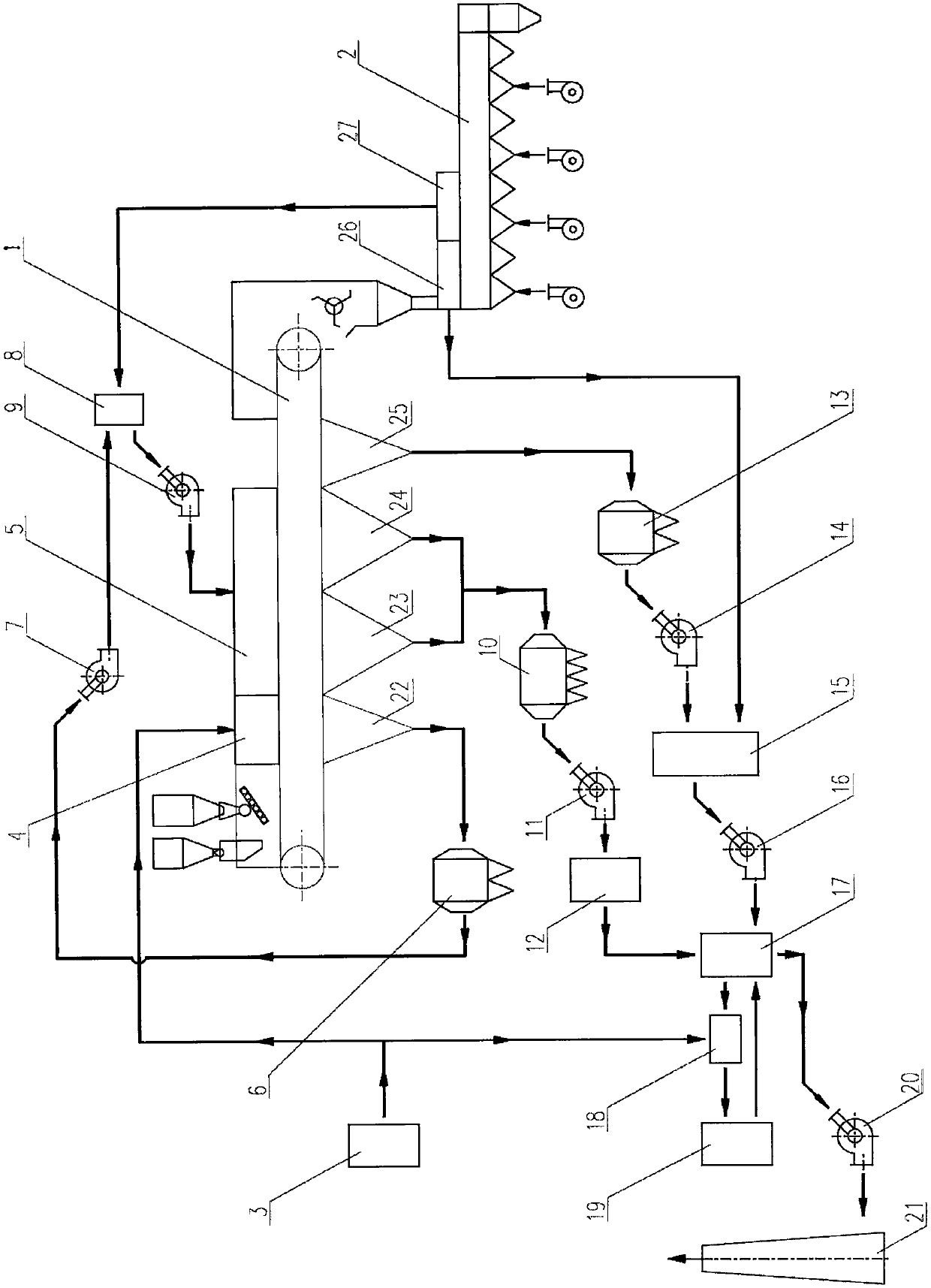
[0035] Take a certain 210m 2 Taking a sintering machine as an example, a detailed description of an environmentally friendly and energy-saving treatment process for a sintering flue gas of the present invention is as follows:

[0036] Such as figure 1 shown in a 210m 2 On the sintering machine 1, the No.1~No.3 bellows flue gas in the ignition area of ​​the head of the sintering machine in the area ① is collected and then passed through the multi-pipe dust collector 6 at the head and led to the circulating flue gas mixing by the flue gas fan 7 at the head. The air box 8 and the flue gas from the upper cover 27 of the 2nd cooling section of the annular cooler 2 are collected to form circulating hot flue gas, and then the circulating flue gas fan 9 leads to the flue gas circulation cover 5 of the sintering machine for flue gas circulation and sintering; the area ② No.4~No.11 bellows flue gas and area in the front area of ​​the sintering machine ③No.12~No.19 air boxes in the rea...


PUM


Abstract

The invention discloses an environmental-protection and energy-conservation treatment technology of sintering flue gas, and belongs to the technical field of energy conservation and environmental protection. Flue gas having high SO2 concentration and very low NOx concentration at a sintering head is subjected to dust removal, and is mixed with hot flue gas in a flue gas hood at a second cooling section of a cooling machine to form circulating hot flue gas, and then flue gas circulating sintering is carried out; flue gas having high SO2 concentration and high NOx concentration at a sintering middle part is subjected to the dust removal and then flue gas desulfurization, the desulfurized flue gas is sintered and cooled by a flue gas heat exchanger, undergoes preheating temperature-rising, then undergoes pipeline complementary combustion temperature-rising to meet the requirement on SCR (Selective Catalytic Reduction) denitration temperature, flue gas denitration is carried out, and the denitrified flue gas is discharged; flue gas having low SO2 concentration and low NOx concentration at a sintering tail is subjected to the dust removal, and is mixed with hot flue gas in the flue gas hood at a first cooling section of the cooling machine to form high-temperature mixed flue gas, the high-temperature mixed flue gas is subjected to heat exchange by the flue gas heat exchanger, the flue gas after being subjected to heat exchange and cooled is directly discharged. According to the treatment technology, the effects of sectional desulfurization and denitration of sintering flue gas, and reduction in flue gas emission are realized; waste heat of the flue gas is used, so that the denitrified flue gas heating consumption is reduced; the construction investment and production running cost are reduced integrally; and the treatment technology corresponds with the running mode of energy conservation, environmental protection, emission reduction, consumption reduction, effect increasing and circular economy.

Description

technical field [0001] The invention belongs to the technical field of environmental protection and energy saving in the sintering production process of the iron and steel metallurgy industry, and relates to an environmental protection and energy saving treatment process for sintering flue gas, in particular to a process for desulfurization and denitrification of sintering flue gas, flue gas circulation sintering and cascaded utilization of waste heat of flue gas Comprehensive treatment process, more specifically related to a method based on SO at different temperatures of flue gas 2 , NO x An environmentally friendly and energy-saving treatment process for sintering flue gas based on the concentration distribution characteristics and flue gas circulation and waste heat utilization treatment process. Background technique [0002] The iron and steel industry is a major energy consumer and also a major polluter. The sintering process is one of the main sources of air pollutan...

Claims


Application Information

Patent Timeline
IPC IPC(8): F27D17/00B01D53/86B01D53/60B01D49/00
CPCB01D49/00B01D53/04B01D53/60B01D53/8637B01D2257/502F27D17/001F27D17/004Y02A50/20
Inventor 郑琨
Owner 安庆沐尔环保科技有限公司
Why Eureka
Try Eureka