Manufacturing method for motion sensor of micro-electro-mechanical system

A motion sensor and micro-electro-mechanical system technology, applied in the field of micro-electro-mechanical systems, can solve problems that threaten the reliability of micro-machines and complex operations, and achieve the effects of low cost, simple preparation process, and improved sensitivity

Inactive Publication Date: 2016-04-27
SUZHOU INST OF NANO TECH & NANO BIONICS CHINESE ACEDEMY OF SCI
View PDF6 Cites 5 Cited by
  • Summary
  • Abstract
  • Description
  • Claims
  • Application Information

AI Technical Summary

Problems solved by technology

However, these methods are complicated to operate, and the problem of adhesion in use still threatens the reliability of micromachines.

Method used


Image

  • Manufacturing method for motion sensor of micro-electro-mechanical system
  • Manufacturing method for motion sensor of micro-electro-mechanical system
  • Manufacturing method for motion sensor of micro-electro-mechanical system

Examples


Embodiment Construction

[0021] Embodiments of the present invention will be described in detail below in conjunction with the accompanying drawings.

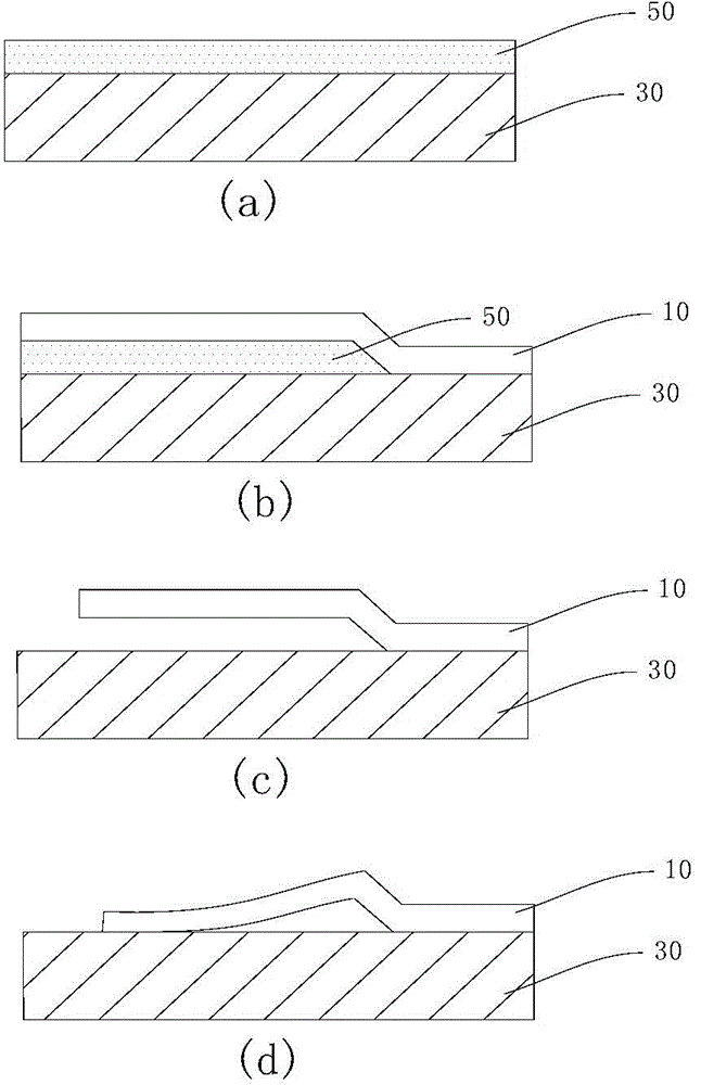
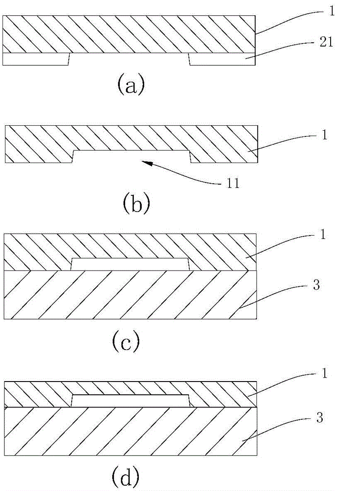
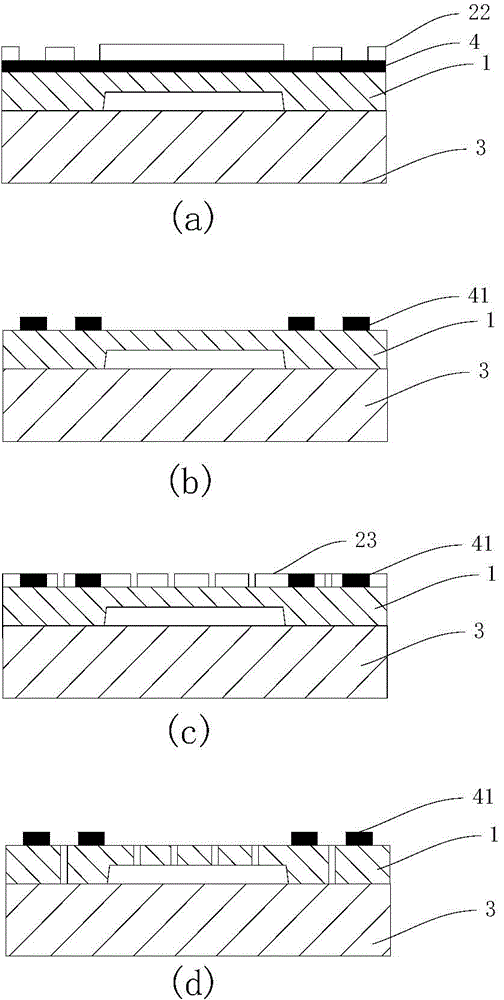
[0022] The present invention provides a method for preparing a micro-electromechanical system motion sensor, for example, it can be used to form a micro-mechanical inertial sensor, and its detailed process is described as figure 2 Shown:

[0023] Step 1: Select a highly doped single crystal silicon wafer 1 as the material of the structural layer. The highly doped single crystal silicon is for improving the conductivity of silicon, and there is no limitation on the doping elements. The fracture strength of single crystal silicon is high, which can make the cantilever beam quality block have good fatigue life when it vibrates. In addition, highly doped silicon also has good electrical conductivity.

[0024] The silicon wafer 1 is cleaned to remove organic pollutants and metal impurities on the surface. Use the photolithography process to carry out t...


PUM


Abstract

The invention relates to the technical field of micro-electro-mechanical systems, in particular to a manufacturing method for a motion sensor of a micro-electro-mechanical system. The method comprises a release process. The release process comprises the specific steps of performing a photoetching process on a silicon wafer on which a top metal electrode is formed to obtain a photoetched graph corresponding to a comb tooth electrode and a mass block; and transferring the photoetched graph onto the silicon wafer by utilizing a deep silicon etching process, and finally removing photoresist with the photoetched graph. According to the method, the problem of adhesion in the release process of a micro-electro-mechanical motion structure can be effectively solved.

Description

technical field [0001] The invention relates to the technical field of micro-electro-mechanical systems, in particular to an improved method for releasing technology of micro-electro-mechanical silicon wafers. Background technique [0002] In the existing micro-electro-mechanical system (MEMS, Micro-Electro-MechanicalSystem, referred to as MEMS) motion sensor technology for releasing the suspended structure, the process of releasing the wet etching is usually used, and the wet etching process is easy to cause the suspended structure and lining after release. Adhesion to the bottom causes device failure. The corrosive liquid used in wet etching needs to be recycled for harmless treatment, which undoubtedly increases the production cost. [0003] MEMS usually includes micro / nano-type basic units such as springs, cantilever beams, films, hinges, and gears. During the fabrication of these typical structures, due to the relative increase in the surface area to volume ratio of mi...

Claims


Application Information

Patent Timeline
IPC IPC(8): B81C1/00
Inventor 余晖俊沈文江李鹏
Owner SUZHOU INST OF NANO TECH & NANO BIONICS CHINESE ACEDEMY OF SCI
Why Eureka
Try Eureka