Electro-optic phase modulator and modulation method

An electro-optical phase modulation and modulator technology, which is applied in the modulation of electro-optic phase modulators and the field of electro-optical phase modulators, can solve the problems of non-constant optical power, low optical power, and performance damage of phase modulators, etc.

Inactive Publication Date: 2016-04-27
IXBLUE
View PDF0 Cites 13 Cited by
  • Summary
  • Abstract
  • Description
  • Claims
  • Application Information

AI Technical Summary

Problems solved by technology

[0015] In fact, however, the measured optical power is not constant and a low variation of the optical power is detected at the exit of the phase modulator
[0016] This residual amplitude modulation or "RAM" proves, in some cases, to be so non-negligible that the performance of the phase modulator is destroyed

Method used


Image

  • Electro-optic phase modulator and modulation method
  • Electro-optic phase modulator and modulation method
  • Electro-optic phase modulator and modulation method

Examples


Embodiment Construction

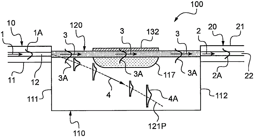
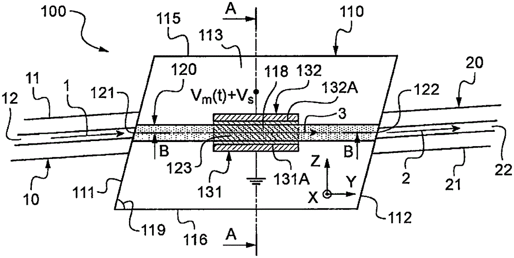
[0052] exist Figures 1 to 8 Different embodiments of electro-optic phase modulators 100 are shown in , along with some variations thereof.

[0053] Typically, such a modulator 100 is intended to modulate a light wave 1 incident on the modulator 100 (here indicated by an arrow, see e.g. figure 1 ) of the optical phase.

[0054] Such a modulator 100 finds many applications in optics, especially in optical fiber electrical communication for data transmission, in interferometric sensors for information processing, or in the dynamic control of laser cavities.

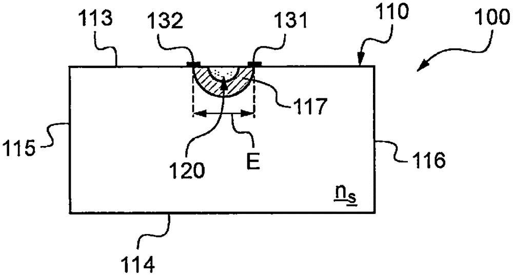
[0055] The modulator 100 first comprises an electro-optic substrate 110, showing first order birefringence reduced by a static or variable electric field, also known as the Pockels effect.

[0056] The electro-optical substrate 110 is preferably formed of lithium niobate crystal with the chemical formula LiNbO3, and this material has a strong Pockels effect.

[0057] Furthermore, the substrate 110 has an optical refracti...


PUM


Abstract

The electro-optic phase modulator intended to modulate the optical phase of a lightwave incident on the modulator, includes an electro-optic substrate having an entrance face and an exit face, an optical waveguide of refractive index (ng) higher than that (ns) of the substrate, continuously rectilinear from a guide entrance end located on the entrance face to a guide exit end located on the exit face, and which is adapted to guide the incident lightwave partially coupled in the waveguide into a guided lightwave propagating along the optical path of the waveguide between the guide entrance end and exit end, and at least two modulation electrodes arranged parallel to the waveguide, so as, when a modulation voltage (Vm(t)) is applied between these modulation electrodes, to introduce a modulation phase-shift, function of the modulation voltage, in the guided lightwave. The phase modulator further includes elements for the electric polarization of the substrate.

Description

technical field [0001] The invention relates generally to the field of optical modulators for controlling optical signals. [0002] It relates more particularly to electro-optical phase modulators intended to modulate the optical phase of light waves incident on the modulator. [0003] The invention also relates to a modulation method for such an electro-optic phase modulator. Background technique [0004] An electro-optical phase modulator is an optoelectronic device that allows control of the optical phase of a light wave incident on and passing through the modulator as a function of an electrical signal applied thereto. [0005] Specific classes of electro-optic phase modulators are known in the art, called integrated modulators or guided optical modulators, which include: [0006] - electro-optic substrates, including entrance and exit faces, [0007] - An optical waveguide which is a continuous straight line from a waveguide entrance end on said entrance face of the ...

Claims


Application Information

Patent Timeline
Patent Type & Authority Applications(China)
IPC IPC(8): G02F1/035
CPCG02F1/035G02F1/225G02F1/0316G02F1/0353G02F1/0356
Inventor H·波尔特N·格罗萨德
Owner IXBLUE
Why Eureka
Try Eureka