Composite-wing vertical take-off and landing unmanned aerial vehicle

A technology of vertical take-off and landing and unmanned aerial vehicles, which is applied in the direction of vertical take-off and landing aircraft, rotorcraft, motor vehicles, etc., to reduce the difficulty of control, improve the control accuracy, and improve the effect of yaw control

Active Publication Date: 2016-05-04
CHENGDU JOUAV AUTOMATION TECH
View PDF6 Cites 19 Cited by
  • Summary
  • Abstract
  • Description
  • Claims
  • Application Information

AI Technical Summary

Problems solved by technology

[0006] Aiming at the control problem of the flight attitude of the compound-wing UAV in the above-mentioned prior art, the present invention provides a compound-wing vertical take-off and

Method used


Image

  • Composite-wing vertical take-off and landing unmanned aerial vehicle
  • Composite-wing vertical take-off and landing unmanned aerial vehicle

Examples


Example Embodiment

[0036] Example 1:

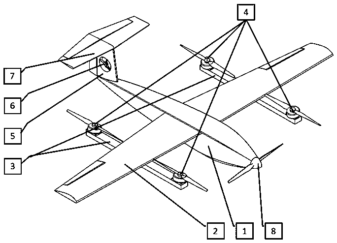
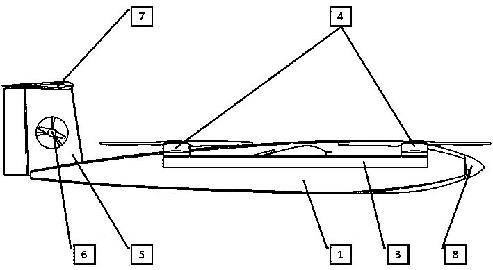
[0037] like figure 1 and figure 2 As shown, a compound wing vertical take-off and landing UAV includes a fuselage 1, a wing 2 fixed on the fuselage 1 and symmetrical to the length direction of the fuselage 1, and a vertical power unit fixed on the wing 2 4 and the level flight power unit 8 fixed on the fuselage 1, also includes a vertical empennage 5 fixed on the fuselage 1, the vertical empennage 5 is also provided with a yaw control unit 6 and a horizontal empennage 7;

[0038] The wing 2 is fixed on the middle section of the fuselage 1, and two ailerons are hinged on the trailing edge of the wing 2, and the two ailerons are located on different sides of the fuselage 1;

[0039] Described vertical power unit 4 is four, and vertical power unit 4 comprises vertical power propeller, motor and electronic governor, and described electronic governor is used for controlling the rotating speed of motor, and described motor is used for braking vertical propelle...

Example Embodiment

[0046] Example 2:

[0047] The present embodiment is further limited on the basis of embodiment 1, as figure 1 and figure 2 As shown, as a specific connection scheme of the vertical power unit 4 on the wing 2, it also includes two power unit installation rods 3 for the fixed connection between the vertical power unit 4 and the wing 2, and the two power unit installation rods 3 are respectively It is fixed on different sides of the fuselage 1, and the length direction of the installation rod is parallel to the length direction of the fuselage 1. A vertical power unit 4 is fixed at the end of each power unit installation rod 3 .

[0048] In the above structure, it is convenient to realize that the two vertical power units 4 on the same side of the fuselage 1 are set far apart without changing the size of the wing 2, so as to change the operating state of a single vertical power unit 4 , to obtain a more benchmark UAV flight state control effect.

[0049] Because the UAV prov...

Example Embodiment

[0057] Example 3:

[0058] This embodiment is further limited on the basis of any one of the technical solutions provided in the above embodiments, in order to facilitate changing the size of the yaw moment and roll moment generated by the wing 2 to the UAV under the high-speed flight state of the UAV , the inclination angle of the aileron and the wing 2, and the inclination angle of the aileron and the fuselage 1 are all adjustable.


PUM

PropertyMeasurementUnit
Spanaaaaaaaaaa

Abstract

The invention discloses a composite-wing vertical take-off and landing unmanned aerial vehicle. A conventional fixed-wing aerodynamic layout is adopted to be combined with an X-shaped four-axis layout, and the aerial vehicle states such as vertical take-off and landing, hovering and high-speed cruising are achieved. The yaw control moment is increased through a variable-pitch propeller installed on a vertical tail and a four-axis motor which is installed on a wing and has a tilt angle, and the robustness and the control precision of the large-rotational-inertia composite-wing unmanned aerial vehicle in the low-speed flying state.

Description

technical field [0001] The invention relates to the technical field of vertical take-off and landing aircraft, in particular to a composite wing vertical take-off and landing unmanned aerial vehicle. Background technique [0002] The fixed-wing vertical take-off and landing UAV takes into account the high-speed flight capability, long-lasting capability and multi-axis UAV vertical take-off and landing capability of the fixed-wing UAV. Therefore, because of its practical value, the fixed-wing vertical take-off and landing Taking off and landing UAVs has been widely respected. [0003] The existing fixed-wing vertical take-off and landing UAVs are generally divided into three types: tilting power type, tail seat type and compound wing type. Among them, the composite wing vertical take-off and landing scheme is based on a conventional fixed-wing aircraft, adding a multi-axis power unit, flying in a multi-axis mode under vertical take-off and landing and low speed conditions, a...

Claims


Application Information

Patent Timeline
IPC IPC(8): B64C27/22B64C5/06B64C29/02B64C9/00
CPCB64C5/06B64C9/00B64C27/22B64C29/02
Inventor 王陈王利光任斌王进
Owner CHENGDU JOUAV AUTOMATION TECH
Why Eureka
Try Eureka