Aviation kerosene production method
A technology of jet fuel and kerosene, which is applied in the field of jet fuel production, can solve problems such as poor quality of jet fuel, achieve better quality and improve quality
- Summary
- Abstract
- Description
- Claims
- Application Information
AI Technical Summary
Problems solved by technology
Method used
Image

Examples
Embodiment 1
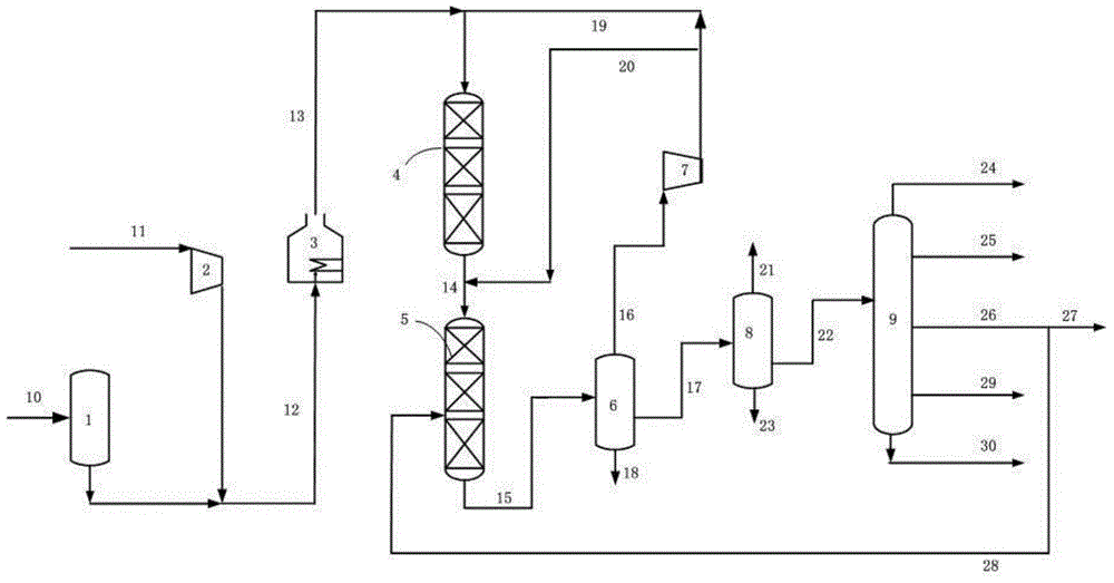
[0068] This embodiment adopts figure 1 The process shown proceeds, specifically:
[0069] The raw oil enters the raw oil storage tank 1 through the pipeline 10, and the new hydrogen is mixed with the raw oil through the pipeline 11 and the gas compressor 2 in turn, and then introduced into the heating furnace 3 through the pipeline 12, and then enters the hydrofining reaction zone 4 through the pipeline 13. The mixed oil hydrogen enters the hydrocracking reaction zone 5 from the pipeline 14 . The raw oil and hydrogen react in the hydrorefining reaction zone and the hydrocracking reaction zone in turn. After heat exchange and cooling, the reaction effluent is introduced into the high-pressure separator 6 through the pipeline 15 for gas-liquid separation. The hydrogen-rich gas at the top of the high-pressure separator The flow enters the circulating hydrogen compressor 7 from the pipeline 16, and after being pressurized by the circulating hydrogen compressor, it is divided into...
Embodiment 2
[0079] The present embodiment adopts the same process as embodiment 1 to carry out, the difference is:
[0080] The reaction conditions adopted in this embodiment are respectively as follows:
[0081] Hydrofining reaction zone: the reaction temperature is 375°C; the reaction pressure is 8MPa; the volume ratio of hydrogen to oil is 800:1; the volume space velocity is 0.5h -1 The top bed is equipped with hydrogenation protection catalyst RG-1 (accounting for 15% of the total amount of catalyst loaded in the hydrofinishing reaction zone), and the rest is equipped with hydrofinishing catalyst RN-32V;
[0082] Hydrocracking reaction zone: the reaction temperature is 378°C; the reaction pressure is 8MPa; the volume ratio of hydrogen to oil is 1200:1; the volume space velocity is 1.0h -1 Divide into three catalyst beds, the first two catalyst beds are filled with the hydrocracking catalyst RHC-3 containing Y molecular sieve, the third bed is filled with the rear refining catalyst RN...
Embodiment 3
[0089] The present embodiment adopts the same process as embodiment 1 to carry out, the difference is:
[0090] The reaction conditions adopted in this embodiment are respectively as follows:
[0091] Hydrofining reaction zone: the reaction temperature is 375°C; the reaction pressure is 10MPa; the volume ratio of hydrogen to oil is 800:1; the volume space velocity is 0.8h -1 The top bed is equipped with hydrogenation protection catalyst RG-1 (accounting for 15% of the total amount of catalyst loaded in the hydrofinishing reaction zone), and the rest is equipped with hydrofinishing catalyst RN-32V;
[0092] Hydrocracking reaction zone: the reaction temperature is 376°C; the reaction pressure is 10MPa; the volume ratio of hydrogen to oil is 1200:1; the volume space velocity is 1.6h -1 Divide into three catalyst beds, the first two catalyst beds are filled with the hydrocracking catalyst RHC-3 containing Y molecular sieve, the third bed is filled with the rear refining catalyst ...
PUM
 Abstract
Description
Claims
Application Information
 - R&D
- Intellectual Property
- Life Sciences
- Materials
- Tech Scout
- Unparalleled Data Quality
- Higher Quality Content
- 60% Fewer Hallucinations
Browse by: Latest US Patents, China's latest patents, Technical Efficacy Thesaurus, Application Domain, Technology Topic, Popular Technical Reports.
© 2025 PatSnap. All rights reserved.Legal|Privacy policy|Modern Slavery Act Transparency Statement|Sitemap|About US| Contact US: help@patsnap.com