A mechanical anode steel claw structure for prebaked aluminum electrolytic cell

An aluminum electrolytic cell and anode steel claw technology, which is applied to the field of aluminum electrolytic anode steel claw, can solve the problems of time-consuming and laborious carbon block replacement process, large contact voltage drop on the connection surface, and reduced electrolysis efficiency, so as to reduce heat loss and save heat energy. , the effect of increasing the contact area

Active Publication Date: 2018-08-14
周俊和 +1
View PDF9 Cites 4 Cited by
  • Summary
  • Abstract
  • Description
  • Claims
  • Application Information

AI Technical Summary

Problems solved by technology

[0005] At present, the traditional anode residue treatment method is to break and fall off the carbon block connected to the conductive rod in the anode assembly workshop, and then break the anode steel bowl cast by phosphorus pig iron to break off the aluminum conductive rod and steel bowl. The claws are used for new carbon blocks, so that the replacement process of the carbon blocks is time-consuming and laborious. At the same time, a large amount of heat on the steel claws is also taken away and cannot be used. When a new anode is inserted into the electrolytic cell It is necessary to reheat the carbon block and steel claw to a certain temperature before they can conduct electricity normally, resulting in waste of heat and reducing the efficiency of electrolysis
[0006] And because of the cast steel claw-carbon block connection method, the contact voltage drop on the connection surface is relatively large, and the temperature of the poured phosphorus pig iron molten iron is about 1600°C. After cooling, there must be a gap between the phosphorus pig iron bowl and the carbon bowl, so the steel claw When the carbon block anode group works in the electrolytic cell, a voltage drop of about 150mv occurs between the steel claw and the contact surface of the carbon block, resulting in an electrical loss of about 400-500 degrees / ton of aluminum

Method used


Image

  • A mechanical anode steel claw structure for prebaked aluminum electrolytic cell
  • A mechanical anode steel claw structure for prebaked aluminum electrolytic cell
  • A mechanical anode steel claw structure for prebaked aluminum electrolytic cell

Examples


Embodiment

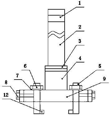
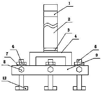
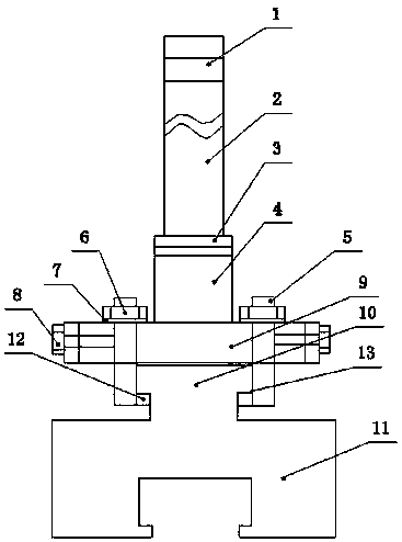
[0023] Embodiment: a kind of mechanical type anode steel claw structure that prebaked aluminum electrolyzer is used, as attached Figure 1-2 As shown, a mechanical steel claw bottom plate 9 is included, and an anode carbon block connection device is provided below the mechanical steel claw bottom plate 9; an anode aluminum guide rod 2 is connected above the mechanical steel claw bottom plate 9.

[0024] A mechanical steel claw bridge foot 4 is provided between the mechanical steel claw bottom plate 9 and the anode aluminum guide rod 2 , and the mechanical steel claw bridge foot 4 is connected to the anode aluminum guide rod 2 through an aluminum-steel explosive welding composite plate 3 .

[0025] The anode carbon block connection device includes movable grooves arranged on both sides of the mechanical steel claw bottom plate 9, the movable groove is provided with mechanical steel claw T-shaped fastening bolts 5, and the mechanical steel claw T-shaped fastening bolts 5 The bot...


PUM


Abstract

The invention discloses a mechanical anode steel claw structure for a prebaking aluminum cell. The mechanical anode steel claw structure comprises a mechanical steel claw base plate (9). An anode carbon block connection device is arranged below the mechanical steel claw base plate. An anode aluminum conducting rod (2) is connected to the portion above the mechanical steel claw base plate (9). The mechanical anode steel claw structure has the advantages that carbon blocks are rapidly replaced, time and labor are saved, heat energy is saved, contact resistance and voltage drop of a steel claw and a carbon block are lowered, and the number of anode carbon block sets is decreased.

Description

technical field [0001] The invention relates to an aluminum electrolytic anode steel claw, in particular to a mechanical anode steel claw structure for a prebaked aluminum electrolytic cell. Background technique [0002] In the modern electrolytic aluminum industry, prebaked anodes are used to produce electrolytic aluminum. The prebaked anode is generally a cuboid with a stable geometric shape. It uses stone tar and pitch coke as the aggregate and coal tar pitch as the binder. It has different sizes according to the size of the electrolytic cell current and the process. Its current density Generally at 0.68-0.9A / cm 2 Within the range, the service life of each carbon block is generally 23-30 days. [0003] In the existing prebaked anode electrolytic aluminum production, the anode steel claws and the anode carbon block are all connected by casting of phosphorus pig iron, and there are 2-4 diameters of 160-180mm on the upper surface of the prebaked anode carbon block in the c...

Claims


Application Information

Patent Timeline
Patent Type & Authority Patents(China)
IPC IPC(8): C25C3/12
CPCC25C3/12
Inventor 邹建明
Owner 周俊和
Why Eureka
Try Eureka