Device and method for production and injection of PLIF flow field diagnosis tracer

A tracer and flow field technology, applied in measurement devices, instruments, fluorescence/phosphorescence, etc., can solve the problems of temperature, air pressure and concentration affecting the accuracy of experiments, unable to accurately determine mixed steam, etc., to achieve stable temperature and flow, realize Precisely controlled, flexible effects

Active Publication Date: 2016-05-04
HARBIN INST OF TECH
View PDF4 Cites 15 Cited by
  • Summary
  • Abstract
  • Description
  • Claims
  • Application Information

AI Technical Summary

Problems solved by technology

[0007] In order to solve the problem that the accuracy of the experiment cannot be accurately determined due to the inability to accurately determine the temperature, pressure and concentration of the mixed gas during the quantitative me

Method used


Image

  • Device and method for production and injection of PLIF flow field diagnosis tracer

Examples


specific Embodiment approach 1

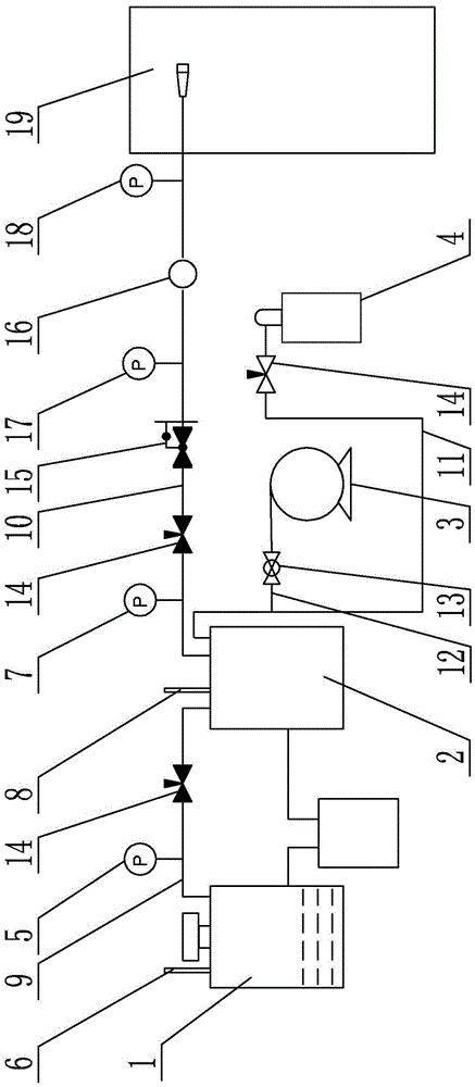
[0021] Specific implementation mode one: combine figure 1 Describe this embodiment, the device in this embodiment includes a generator tank 1, a gas mixing tank 2, a vacuum pump 3, a dilution gas bottle 4, a first pressure gauge 5, a first thermocouple 6, a second pressure gauge 7, a second Thermocouple 8, first gas pipeline 9, second gas pipeline 10, third gas pipeline 11, fourth gas pipeline 12, ball valve 13, three needle valves 14, multiple first heating coils and multiple second heating coil;

[0022] The generating tank 1 communicates with the gas mixing tank 2 through the first gas pipeline 9, the generating tank 1 is provided with a first thermocouple 6, and the gas mixing tank 2 is provided with a second thermocouple 8, so The first pressure gauge 5 is installed on the first gas pipeline 9, the gas mixing tank 2 communicates with the dilution gas bottle 4 through the third gas pipeline 11, and the third gas pipeline 11 communicates with a fourth One end of the gas p...

specific Embodiment approach 2

[0026] Specific implementation mode two: combination figure 1 To illustrate this embodiment, in this embodiment, the first gas transmission pipeline 9 , the second gas transmission pipeline 10 and the fourth gas transmission pipeline 12 are all wound with heating coils.

[0027] In this embodiment, the purpose of wrapping the entire gas pipeline with a heating coil is to ensure that the tracer vapor does not liquefy during transportation. Other unmentioned structures and connections are the same as those in the first embodiment.

specific Embodiment approach 3

[0028] Specific implementation mode three: combination figure 1 Describe this embodiment. In this embodiment, the device also includes a pressure reducing valve 15, a gas mass flow meter 16, a third pressure gauge 17, and a fourth pressure gauge 18. A pressure reducing valve 15 and a gas mass flow meter 16 are arranged in turn from one end of the tank 2 to the gas outlet end, and a third pressure gauge 17 and a fourth pressure gauge 18 are also installed on the second gas pipeline 10. The pressure gauge 17 is located between the pressure reducing valve 15 and the gas mass flow meter 16, and the fourth pressure gauge 18 is located between the gas mass flow meter 16 and the gas outlet port. In this embodiment, the purpose of connecting the pressure reducing valve 15 and the gas mass flow meter 16 on the gas mixing tank 2 is to control the outflow speed of the mixed gas so as to put it into the experimental field 19 . Other unmentioned structures and connections are the same as ...


PUM


Abstract

Relating to a device and method for production and injection of a tracer, the invention provides a device and method for production and injection of a PLIF (planar laser induced fluorescence) flow field diagnosis tracer. During high-time and high-spatial resolution quantitative measurement of mixed fuel gas by a PLIF diagnostic technique, experimental accuracy can be affected due to the incapability of accurate determination of mixed steam's temperature, pressure and concentration. According to the invention, a generation tank is communicated with a gas mixing tank through a first gas transmission pipeline, the generation tank is equipped with a first thermocouple, and the gas mixing tank is equipped with a second thermocouple. The method provided by the invention consists of: step 1. formation of pure tracer steam; step 2. adjustment of mixed gas concentration; step 3. pressurization and dilution of diluent gas in the gas mixing tank according to an ideal gas state equation PV=nRT, thus obtaining a mixed gas meeting the experiment required concentration of A, temperature of T and pressure of P; and step 4. injection of the mixed gas. The device and the method provided by the invention are used for the process of tracer production and injection into an experimental field.

Description

technical field [0001] The invention relates to a device and method for generating and injecting a tracer, and belongs to the technical field of laser spectrum application. Background technique [0002] PLIF [Plane Laser Induced Fluorescence Technology, PlannerLaserInducedFluorescence] as a laser spectroscopy technology is currently mainly used in the diagnosis of high-speed combustion fields in engines. [0003] In the process of engine research, sufficient mixing of fuel and oxidant is a necessary condition for combustion. The uniformity and equivalence ratio of fuel and oxidant will have a great impact on engine ignition, flame propagation speed and flame stability. Therefore, the quantitative measurement of the mixed gas with high time and high spatial resolution is the key to develop the engine. However, traditional measurement methods, such as the old-fashioned probe test method, interfere with the original flow field, and the time resolution of the measurement is al...

Claims


Application Information

Patent Timeline
IPC IPC(8): G01N21/64
CPCG01N21/6402
Inventor 彭江波于欣常光马欲飞李晓晖杨超博于杨杨振周淼樊荣伟李旭东董志伟闫仁鹏
Owner HARBIN INST OF TECH
Why Eureka
Try Eureka