High-precision radius of curvature testing device and method

A technology of radius of curvature and testing equipment, which is applied in the direction of measuring equipment, electrical equipment, instruments, etc., can solve the problems of easy scratches on the surface of the tested optical components, difficult detection uncertainty, etc., to reduce the error of the non-sensing area, Avoid being scratched and reduce the effect of empty stroke error

Inactive Publication Date: 2016-05-11
CHANGCHUN INST OF OPTICS FINE MECHANICS & PHYSICS CHINESE ACAD OF SCI
View PDF6 Cites 2 Cited by
  • Summary
  • Abstract
  • Description
  • Claims
  • Application Information

AI Technical Summary

Problems solved by technology

[0003] The purpose of the present invention is to propose a high-precision curvature radius testing device and method to solve the existing problems in the prior art that the surface of the optical element to be tested is easily scratched and it is difficult to achieve sub-micron detection uncertainty. Digital interferometer and high-precision dual-frequency laser interferometric displacement measurement system are built to realize non-contact and non-destructive testing of the curvature radius of the tested optical spherical mirror with high precision

Method used


Image

  • High-precision radius of curvature testing device and method
  • High-precision radius of curvature testing device and method

Examples


Embodiment Construction

[0022] Embodiments of the present invention will be further described below in conjunction with the accompanying drawings.

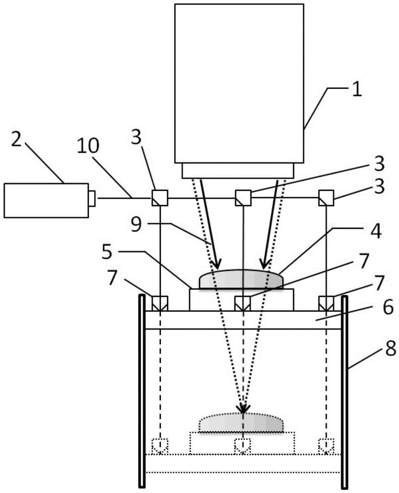
[0023] See attached figure 1 , a high-precision curvature radius testing device of the present invention includes an interferometric system 1, a dual-frequency laser 2, a light guide element 3, a translation tilt adjustment table 5, a Z-direction mobile table 6, a reflection pyramid 7 and a guide rail 8;

[0024] The translation and inclination adjustment table 5 is arranged on the Z-direction mobile table 6, and any two opposite side walls of the Z-direction mobile table 6 slide up and down in cooperation with the guide rail 8, and the tested spherical mirror 4 is arranged on the translation table 6. On the tilt adjustment table 5, three reflective pyramids 7 are uniformly arranged on the upper surface of the Z-direction mobile platform 6, and a light guide element 3 is arranged at a vertical position above each reflective pyramid 7, and the light radia...


PUM


Abstract

The invention belongs to the technical field of optical element geometrical parameter measurement, relates to a high-precision radius of curvature testing device and method, and aims to solve the problem existing in the prior art that a surface of a tested optical element is easy to scratch and submicron-grade detection of uncertainty is difficult to reach. A translation inclination adjusting table is arranged on a Z-direction moving table, any two opposite side walls of the Z-direction moving table are matched with guide rails and slide up and down, a tested spherical mirror is arranged on the translation inclination adjusting table, an upper surface of the Z-direction moving table is uniformly provided with a plurality of reflection pyramids, an upper side vertical position of each reflection pyramid is provided with a light guiding element, light radiated by an interference measurement system is reflected by the tested spherical mirror to form an interference measurement optical path, the interference measurement optical path passes through the interference measurement system and an interferogram is to obtained, laser emitted by a dual-frequency laser is split into multiple beams through the plurality of light guiding elements, laser after beam splitting is vertically incident to the plurality of reflection pyramids, and after reflection by the plurality of reflection pyramids, a dual-frequency laser interference displacement measurement optical path is formed.

Description

technical field [0001] The invention belongs to the technical field of geometric parameter measurement of optical elements, and in particular relates to a high-precision curvature radius testing device and method. Background technique [0002] The radius of curvature of an optical spherical mirror is a basic parameter of an optical element. Extreme ultraviolet lithography-related technologies can detect and process optical spherical mirrors with extremely high precision, reaching sub-micron levels. The measurement methods of the radius of curvature are divided into two types: contact measurement and non-contact measurement. Among them, the contact measurement methods mainly include the template method, the spherometer method and the coordinate measuring machine method, and the non-contact measurement methods mainly include laser tracker and laser Interferometer combined method and interferometric test cat's eye-confocal method. The test accuracy of the template method and ...

Claims


Application Information

Patent Timeline
Patent Type & Authority Applications(China)
IPC IPC(8): G01B7/293
CPCG01B7/293
Inventor 张文龙苗亮刘钰于杰张海涛马冬梅金春水
Owner CHANGCHUN INST OF OPTICS FINE MECHANICS & PHYSICS CHINESE ACAD OF SCI
Why Eureka
Try Eureka