
Television control system based on brain-computer interface technology

A technology of TV control and computer interface, applied in the input/output, electrical components, computer parts, etc. of user/computer interaction, which can solve the problem of unfavorable practical application of BCI system, unresearched practical functions, and large size of visual stimulators and other issues, to achieve the effect of reducing hardware development costs, facilitating manufacturing and use, and reducing complexity

Inactive Publication Date: 2016-05-11
XIAN UNIV OF SCI & TECH
View PDF14 Cites 4 Cited by
  • Summary
  • Abstract
  • Description
  • Claims
  • Application Information

AI Technical Summary

Problems solved by technology

[0004] 1. Most of the traditional BCI systems use flashing diodes or displays to generate visual stimuli. The size of the visual stimulator is large and the mobility is poor, so it is not conducive to the practical application of the BCI system.
[0005] 2. Due to the use of PC for data analysis and LED as stimulation module, the system is scattered and huge
[0006] 3. The communication between the PC and the lower computer depends on the serial port line, and the overall volume and quality are relatively large, so it is not conducive to movement and portability
[0007] 4. The previous design was only experimental technical research, such as: using the BCI system to do some simple control, moving the cursor on the computer screen, etc., and more practical functions have not yet been studied

Method used


Image

  • Television control system based on brain-computer interface technology
  • Television control system based on brain-computer interface technology
  • Television control system based on brain-computer interface technology

Examples


Embodiment Construction

[0040] The present invention will be specifically introduced below in conjunction with the accompanying drawings and specific embodiments.

[0041] The control system of the present invention takes the set-top box of radio and television as the control target, and the control target is wide because the coding format of the remote control of the set-top box is compatible.

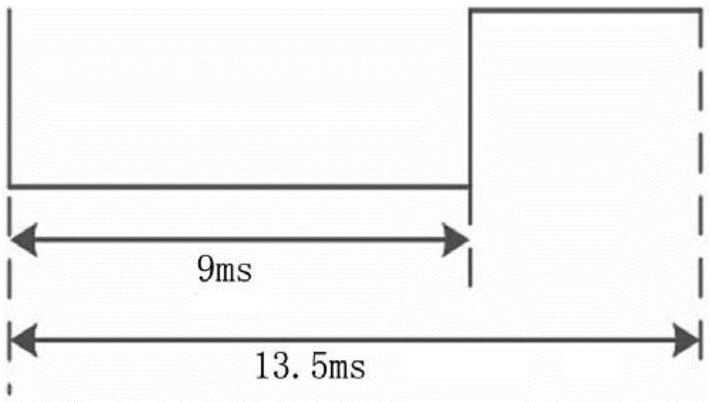
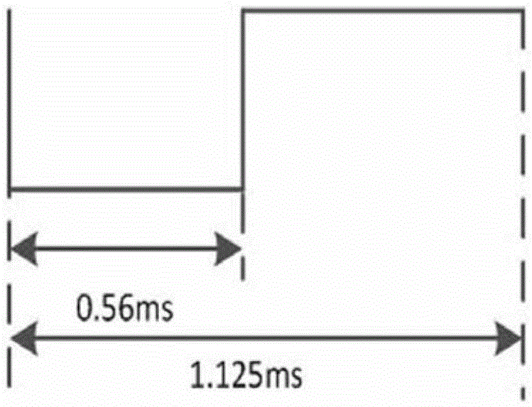
[0042] Since the code of the set-top box remote control of radio and television adopts 32 bits, it is necessary to decode the remote control code of the set-top box remote control.

[0043] A general infrared remote control system consists of three parts: an infrared remote control signal transmitter, an infrared remote control signal receiver, a microcontroller and its peripheral circuits.

[0044] Among them, the infrared remote control signal transmitter is used to generate remote control code pulses. Drive the infrared emitting tube to output the infrared remote control signal, and the remote control re...


PUM


Abstract

The invention discloses a television control system based on a brain-computer interface technology. The television control system is characterized by comprising a brainwave signal gatherer, an Android mobile phone and an ARM processor, wherein the brainwave signal gatherer is used for gathering stable-state visual induced signals generated by the brain of a user and sending the acquired stable-state visual induced signals to the Android mobile phone in a wireless mode; the Android mobile phone is used for stimulating the visual sense of the user, performing analysis processing on the received stable-state visual induced signals and sending control commands to the ARM processor in a wireless mode; and the ARM processor is used for converting instructions and sending corresponding infrared signals to a television set top box after receiving the control commands so as to complete control motion once. The system provided by the invention has the following advantages: the system is composed of the brainwave signal gatherer, the Android mobile phone and the ARM processor, and the modularization degree is high; a conventional visual stimulator and a PC are replaced by use of the Android mobile phone, the dimension is small, the mobility is good, and the development cost is low; and the set top box is taken as a control object, and the practicality is high.

Description

technical field [0001] The invention relates to a television control system, in particular to a television control system based on brain-computer interface technology. Background technique [0002] Brain-computer interface (BCI) technology, as a technology to realize the direct communication of information between the brain and external devices (computer or external environment, etc.), has developed by leaps and bounds in recent years, and has been used in biomedicine, virtual reality, Fields such as game entertainment and rehabilitation engineering have shown important values. [0003] At present, most brain-computer interface systems (BCI systems for short) are developed by combining a PC with a medical brainwave tester. The system consists of three parts: a visual stimulator, a PC and a brainwave tester. Such systems mainly exist Some of the following questions: [0004] 1. Most of the traditional BCI systems use flashing diodes or displays to generate visual stimuli. T...

Claims


Application Information

Patent Timeline
Patent Type & Authority Applications(China)
IPC IPC(8): H04N21/422G06F3/01
CPCH04N21/4222H04N21/42221H04N21/42222G06F3/015
Inventor 汪梅贺开明程松赵海强
Owner XIAN UNIV OF SCI & TECH
Learn More