
Pulse optical fiber laser and method for realizing time domain pulse slicing by using the same

A technology of fiber lasers and lasers, applied in lasers, laser components, phonon exciters, etc., can solve problems such as unpredictable and uncontrollable physical properties

Inactive Publication Date: 2016-05-18
FOSHAN UNIVERSITY
View PDF2 Cites 12 Cited by
  • Summary
  • Abstract
  • Description
  • Claims
  • Application Information

AI Technical Summary

Problems solved by technology

[0004] However, in some special application fields, such as the field of time-domain precision measurement and entanglement coding technology, not only the pulse train repetition rate is adjustable, but also a certain binding ability between adjacent pulses and adjustable pulse spacing are required. characteristics, the above methods cannot meet these requirements
At present, some physical methods have also been reported to achieve a certain binding capacity between pulse clusters [Document 4.M. [Document 5.W-C.Chenetal, Opt.FiberTechnol.20(3),199–207(2014)], however, the physical properties of the confinement ability and adjustable pulse interval obtained by these techniques are unpredictable and unpredictable controlling

Method used


Image

  • Pulse optical fiber laser and method for realizing time domain pulse slicing by using the same
  • Pulse optical fiber laser and method for realizing time domain pulse slicing by using the same
  • Pulse optical fiber laser and method for realizing time domain pulse slicing by using the same

Examples


Embodiment 1

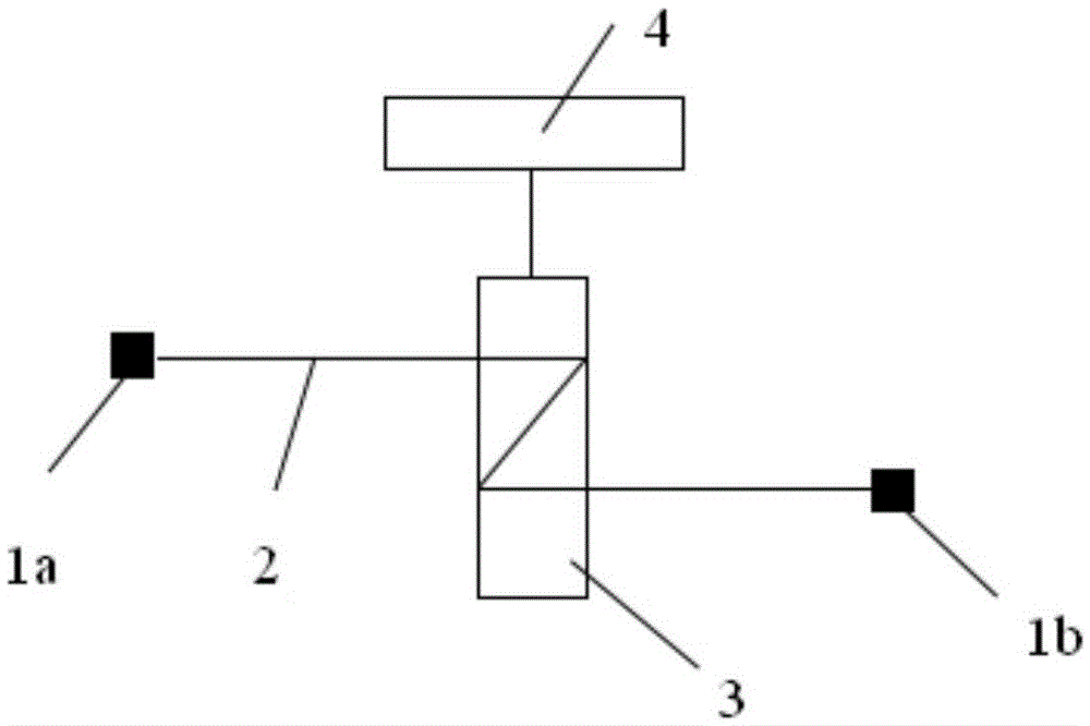
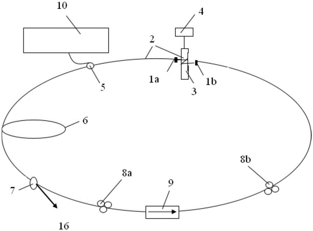
[0033] Such as figure 1 and figure 2As shown, the pulsed fiber laser includes a pumping laser 10, a gain fiber 6, a fiber coupler 7, a polarization-dependent isolator 9, a wavelength division multiplexer 5, a first polarization controller 8a and a second polarization controller 8b, the main The resonant cavity is a ring cavity, and a microcavity is also provided in the main resonant cavity, and the microcavity includes a first cavity mirror 1a, a second cavity mirror 1b, a single-mode optical fiber 2, a piezoelectric ceramic 3 and an external control device connected to the piezoelectric ceramic 3. A voltage module 4, a single-mode optical fiber 2 wound on a piezoelectric ceramic 3 and its two ends are respectively connected to the first cavity mirror 1a and the second cavity mirror 1b, the pumping laser 10 is connected to an input end of the wavelength division multiplexer 5, the second A cavity mirror 1a is connected to the other input end of the wavelength division multip...

Embodiment 2

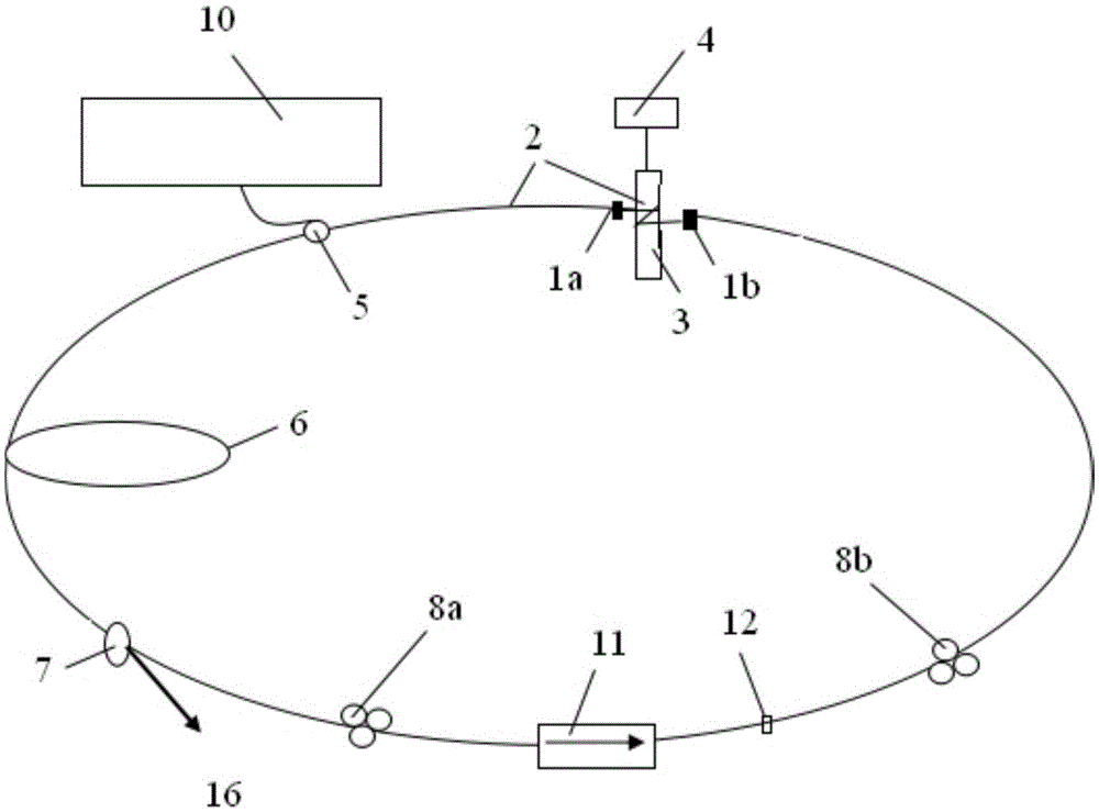
[0037] pulsed fiber lasers, such as image 3 As shown, the main resonant cavity is a ring cavity, except that the polarization-independent isolator 11 and the saturable absorber 12 are sequentially connected between the first polarization controller 8a and the second polarization controller 8b. 1 is exactly the same.

[0038] The saturable absorber 12 adopts commercial graphene, and can also be carbon nanotubes, black phosphorus, topological insulators, sulfide series two-dimensional materials, selenide series two-dimensional materials, semiconductor absorber materials, gold or silver nanorods one-dimensional Material, alcohol or composite inks, which can also be self-prepared, function to generate self-starting pulses through the optical saturable absorption effect.

[0039] The pulsed fiber laser of Example 2 is used for time-domain pulse slicing, and the saturable absorber 12 is used to replace the non-linear polarization rotation effect of Example 1. The physical effect o...

Embodiment 3

[0041] pulsed fiber lasers, such as Figure 4 As shown, the main resonant cavity is an "8" shaped cavity, except that there is no polarization-dependent isolator 9, and a 2×2 fiber coupler 13 with a splitting ratio of 3dB and a polarization-independent isolator 11 are added, all other components are exactly the same as in Embodiment 1. same,

[0042] The two fiber ends on the same side of the 2×2 fiber coupler 13 are respectively butted to form an "8" shape, which constitutes the main resonant cavity of the fiber laser. The pump laser 10 is connected to an input end of the wavelength division multiplexer 5, along the The output end of the wavelength division multiplexer 5 is sequentially connected to the gain fiber 6, one fiber end on the left side of the 2×2 fiber coupler 13, and the other fiber end on the left side of the 2×2 fiber coupler 13 is connected to the first polarization controller 8a , the first polarization controller 8a is connected to the other input end of th...


PUM


Abstract

The invention discloses a pulse optical fiber laser including a pumping laser, a main resonant cavity, and a gain optical fiber arranged in the main resonant cavity. A micro-cavity is arranged in the main resonant cavity and includes a first cavity lens, a second cavity lens, a single mode optical fiber, a piezoelectric ceramic and an external control voltage module connected to the piezoelectric ceramic. The invention also discloses a method for realizing time domain pulse slicing by using the pulse optical fiber laser. The external control voltage module controls a voltage applied to the piezoelectric ceramic, so that the single mode optical fiber generates change in a longitudinal direction, thereby causing dynamic change of the micro-cavity length and performing dynamic slicing with continuous adjustable time domain interval and slice number on a single pulse. The micro-cavity of the pulse optical fiber laser is not limited by an embedded position, can perform effective and controllable dynamic slicing on the single pulse with an ns-ps order, and is widely applied to the ultrafast laser technical field, the optical fiber optics field and the time domain precision measurement field.

Description

technical field [0001] The invention relates to the technical field of fiber lasers, in particular to a pulsed fiber laser and a method for realizing time-domain pulse slicing. Background technique [0002] There are active and passive methods for generating pulses in fiber lasers. Among them, the active way is to add various modulators in the laser cavity to generate pulses. The pulse repetition rate and pulse interval generated by the active mode are determined by the modulator and are controllable, but the pulse width generated by it is relatively large, and the system cost is expensive. The passive method is to introduce saturable absorbers and quasi-saturated absorbers of various materials into the laser cavity to generate pulses. The pulse width generated by the passive method is smaller, but the repetition rate of the fundamental frequency is generally lower. The fundamental frequency repetition rate of a passive fiber laser is determined by the cavity length, whic...

Claims


Application Information

Patent Timeline
IPC IPC(8): H01S3/105H01S3/10H01S3/067
CPCH01S3/06712H01S3/0675H01S3/10023H01S3/10061H01S3/105H01S3/1061
Inventor 陈伟成
Owner FOSHAN UNIVERSITY
Learn More