Spherical light focusing space solar power station

A spherical concentrator and solar cell array technology, applied in the field of solar energy, can solve problems such as low effective light receiving area and complex adjustment of multiple sets of mirrors, achieve high light collection efficiency, low connection structure quality, and reduce design difficulty

Active Publication Date: 2016-05-18
XIDIAN UNIV
View PDF2 Cites 12 Cited by
  • Summary
  • Abstract
  • Description
  • Claims
  • Application Information

AI Technical Summary

Problems solved by technology

The biggest disadvantage of the ALPHA solution is that the adjustment of multiple sets of mirrors is c

Method used


Image

  • Spherical light focusing space solar power station
  • Spherical light focusing space solar power station
  • Spherical light focusing space solar power station

Examples


Embodiment 1

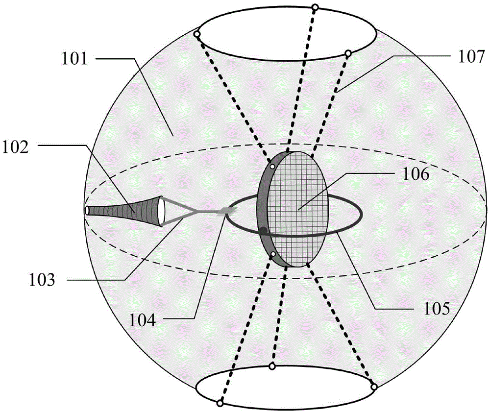
[0035] see figure 1 , the present invention provides a spherical concentrating space solar power station, which consists of a spherical concentrator 101, a solar cell array 102, a transmission cable 103, a conductive slide 104, a conductive slip ring 105, a microwave transmitting antenna 106 and a traction cable 107 Composition; the solar cell array 102 is connected with the conductive slide 104 through the transmission cable 103, the conductive slide 104 is connected with the conductive slip ring 105 for flexible sliding connection, the conductive slip ring 105 is connected with the microwave transmitting antenna 106, and the microwave transmitting antenna 106 is connected by traction The cable 107 is connected to the spherical concentrator 101 . This embodiment adopts a spherical concentrator, which has high light collection efficiency. At the same time, the spherical shape is any axisymmetric rotator, and the light collection fluctuation is small; and the solar cell array a...

Embodiment 2

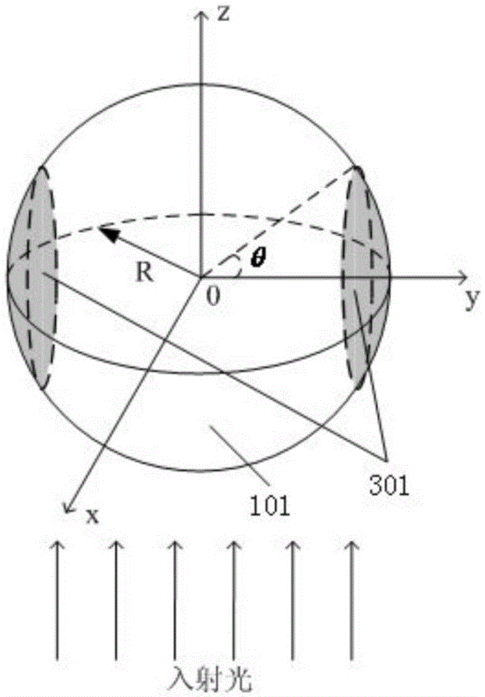
[0038] On the basis of Embodiment 1, in order to ensure the light collection rate, the spherical concentrator 101 removes the spherical cap region (301) on the spherical surface and the lower top, and the radius of the spherical concentrator (101) is:

[0039]

[0040] In the formula, η is the average light collection rate of the concentrator, C is the space solar power density, C=1368W / m 2 , θ is the angle between the center of the spherical cap and the line connecting the center of the spherical concentrator 101 and the boundary of the spherical cap and the line connecting the center of the spherical concentrator 101, that is, θ is the boundary angle of the spherical cap area 301; W is the angle between the line between a certain point on the spherical cap and the center of the ball and the line between the center of the spherical cap and the line between the center of the ball; W is the sunlight collection power required by the system design (for example, the system to b...


PUM


Abstract

The invention belongs to the field of solar technology, and particularly provides a spherical light focusing space solar power station. The solar power station is composed of a spherical condenser (101), a solar cell array (102), a transmission cable (103), a conductive slip plate (104), a conductive slip ring (105) a microwave transmitting antenna (106) and a traction cable (107). The solar cell array (102) is connected with the conductive slip plate (104) through the transmission cable (103). The conductive slide plate (104) is flexibly and slidably connected with the conductive slip ring (105). The conductive slip ring (105) is connected with the microwave transmitting antenna (106). The microwave transmitting antenna (106) is connected with the spherical condenser (101) through the traction cable (107). The spherical light focusing space solar power station has advantages of improving solar energy collection efficiency, reducing length of the transmission cable and mass of a connecting structure between the transmission cable and the condenser, and reducing design difficulty of a heat radiation system.

Description

technical field [0001] The invention belongs to the technical field of solar energy, and in particular relates to a spherical concentrating space solar power station. Background technique [0002] In 1968, Dr. Peter Glaser of the United States proposed the concept of Space Solar Power Station (SSPS). SSPS is a system that collects and converts solar energy into electrical energy in space, and then transmits it back to the ground through wireless energy transmission devices. [0003] There are two types of space solar power plants: non-concentrating and concentrating. Typical cases of non-concentrating SSPS include the American 1979 benchmark system and the European 2001 solar sail system. 1979SSPS is a 10km×5km×0.5km solar panel, which can receive 70GW of energy and obtain 9GW of direct current. One end of the battery board is connected to a microwave transmitting antenna with a diameter of 1km. The attitude control system keeps the battery panel always pointing to the s...

Claims


Application Information

Patent Timeline
IPC IPC(8): H02S10/00H02S40/22H02S40/34H02S40/36
CPCY02E10/52H02S10/00H01L31/0508H02S40/00
Inventor 杨阳张逸群段宝岩黄进李勋王东旭樊冠恒
Owner XIDIAN UNIV
Why Eureka
Try Eureka