Current sensors, power conversion devices
A technology of power conversion device and current sensor, which is applied in the direction of output power conversion device, emergency protection circuit device, measuring device, etc. It can solve the problems of broken wiring and damaged connecting wiring, etc., and achieve the effect of suppressing layout space and cost
- Summary
- Abstract
- Description
- Claims
- Application Information
AI Technical Summary
Problems solved by technology
Method used
Image


Examples
no. 1 approach
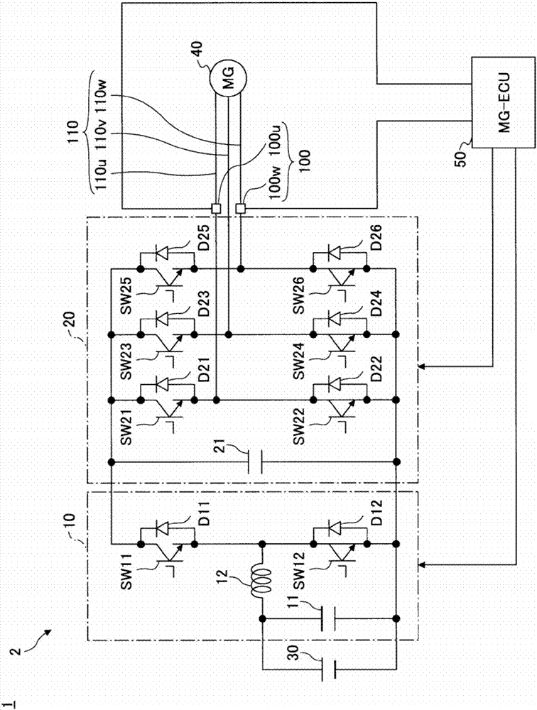
[0040] figure 1 It is a block diagram showing the system configuration of the vehicle 1 including the current sensor 100 and the current conversion device 2 according to the first embodiment.
[0041] The vehicle 1 is an electric vehicle having an electric motor as one of the driving sources. In addition, the vehicle 1 may be a hybrid vehicle equipped with an engine at the same time, or may be an electric vehicle using only an electric motor as a driving source.
[0042] The vehicle 1 includes a battery 30, a motor generator (hereinafter referred to as MG) 40, a power conversion device 2, an MG-ECU 50, a current sensor 100, and the like.
[0043] The battery 30 is a power storage device that supplies electric power to the MG 40. Although, for example, a lithium ion battery or a nickel-hydrogen battery can be used, it is not limited to these batteries, and any secondary battery can be used, and a capacitor can also be used.
[0044] The MG40 is both a rotary electric motor, which is o...
no. 2 approach
[0076] Next, the second embodiment will be described.
[0077] The current sensor 100 according to this embodiment mainly includes a current detection unit that detects the currents of the two connection wires 110u and 110v of the U-phase and V-phase, and the disconnection that breaks the two connection wires 110u and 110v. It is different from the first embodiment in that the thread mechanism is accommodated (unified) in the same housing. Hereinafter, the same constituent elements as those of the first embodiment will be denoted by the same reference numerals, and the description will be focused on different parts.
[0078] Since the current sensor 100 according to this embodiment and the system configuration of the vehicle 1 including the power conversion device 2 are the same as those of the first embodiment except for the arrangement of the current sensor 100 figure 1 The same, so the description is omitted.
[0079] Hereinafter, the current sensor 100 according to this embodime...
no. 3 approach
[0100] Next, the third embodiment will be described.
[0101] The current sensor 100 according to the present embodiment is the same as the second embodiment, and unified the two-phase current detection unit and the disconnection mechanism in the three-phase AC connection wiring from the power conversion device 2 to the MG 40. The difference from the second embodiment is that the power conversion device 2 according to this embodiment supplies three-phase AC power to two MG40s (MG40a, MG40b), and the current sensor according to this embodiment further supplies two three-phase AC powers. In the AC connection wiring, the current detection unit and disconnection mechanism for each two-phase are unified. Hereinafter, the same components as those in the first and second embodiments are denoted by the same reference numerals, and the description will be centered on different parts.
[0102] Image 6 This is a block diagram showing the system configuration of the current sensor 100 and th...
PUM
 Abstract
Description
Claims
Application Information