A pressure roller mobile granulator

A mobile, granulator technology, applied in the direction of die extrusion granulation, solid fuel, biofuel, etc., can solve the problems of production time consumption, rising production cost, time-consuming and labor-intensive effects, etc., to reduce downtime adjustment time, reduce The effect of equipment failure rate and cost reduction of wearing parts

Active Publication Date: 2018-01-09
ANHUI HUANTAI BIO ENERGY TECH DEV
View PDF4 Cites 0 Cited by
  • Summary
  • Abstract
  • Description
  • Claims
  • Application Information

AI Technical Summary

Problems solved by technology

[0003] The common granulator, whether it is a ring die granulator or a flat die granulator, has strict requirements on the moisture content of the feed material. It is often difficult to form and granulate effectively when the moisture content of the raw material is higher than 18%. The yield of pellet molding is also very low
At this time, it is often necessary to add a drying procedure before feeding, but drying requires additional energy, which leads to high production costs
Moreover, in the existing designs of biomass pellet machines, the pressure roller bearings are usually installed inside the pressure rollers, and the pressure rollers are in the forming cavity. The harsh environment of high temperature, high humidity and high dust in the forming cavity often leads to extreme It is easy to be damaged, and this design requires frequent oiling and maintenance of the pressure roller bearings, which is time-consuming and laborious and the effect is not obvious
In addition, due to the wear of the pressure roller, the existing granulator needs to be shut down frequently to adjust the gap between the pressure roller and the mold, and when the granulator is overloaded, it also needs to be shut down, and the molding cavity material must be cleaned before restarting. It not only takes up a lot of manpower, but also consumes a lot of production time, which invisibly makes the production cost further increase

Method used


Image

  • A pressure roller mobile granulator
  • A pressure roller mobile granulator

Examples


Embodiment Construction

[0019] The embodiments of the present invention are described in detail below. This embodiment is implemented on the premise of the technical solution of the present invention, and detailed implementation methods and specific operating procedures are provided, but the protection scope of the present invention is not limited to the following implementation example.

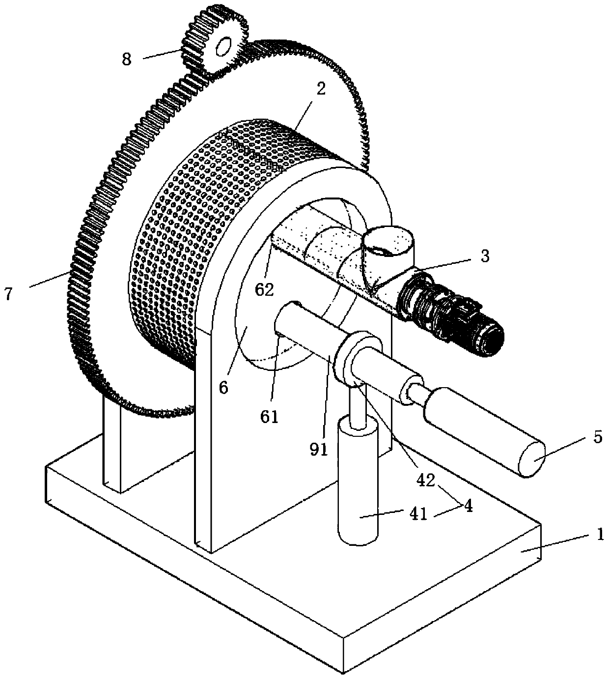
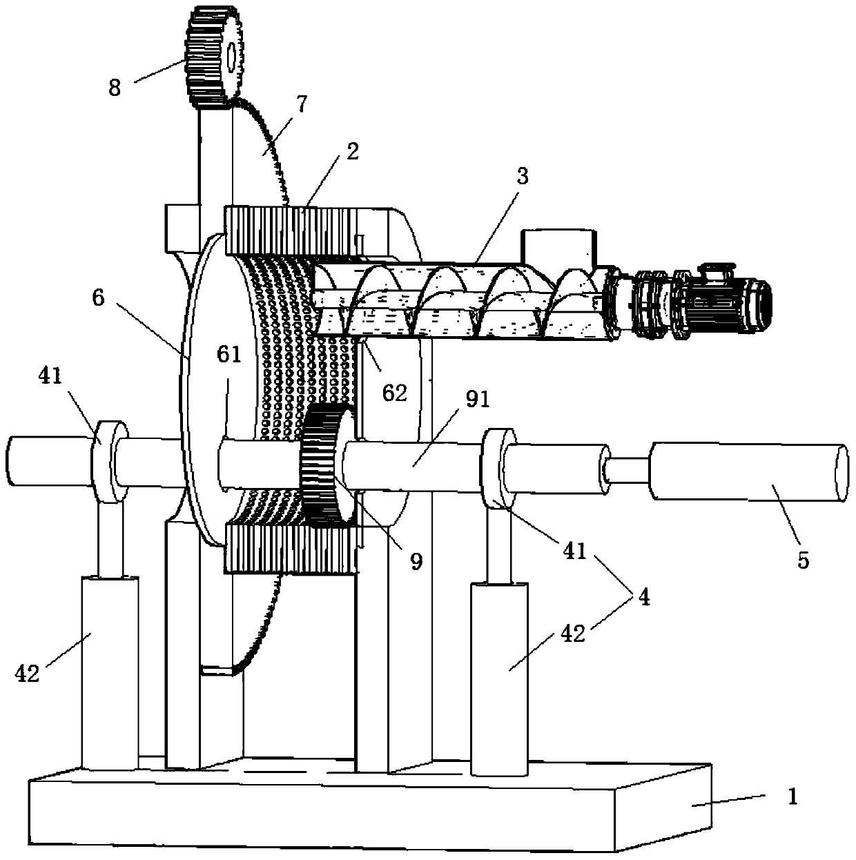
[0020] Such as Figure 1 to Figure 2 As shown, a pressure roller mobile granulator includes a base 1, a ring mold 2, a pressure roller 9 and a pressure roller shaft 91, the ring mold 2 is vertically arranged above the base 1, and the ring mold 2 is a moving mold, which can Under the action of the motor, it rotates around its axis, the inner cavity of the ring die 2 forms a molding cavity, and the pressure roller 9 is fixed in the molding cavity through the pressure roller shaft 91. It is characterized in that: the two ends of the pressure roller shaft 91 protrude from the molding cavity The tightening mechanism 4 ...


PUM


Abstract

The invention discloses a pressure roller mobile granulator, which comprises a base, a ring die, a ring die connecting seat, a pressure roller and a pressure roller shaft, the ring die is vertically arranged above the base, the ring die is a moving die, and the inside of the ring die The cavity forms a forming cavity, and the pressure roller is fixed in the forming cavity through the pressure roller shaft. There is a clearance fit between the pressing mechanism, and one end of the pressing roller shaft is connected with the pushing mechanism, which can drive the pressing roller shaft to reciprocate along the axial direction of the pressing roller shaft, and the width of the pressing roller is smaller than the width of the ring die. Compared with the prior art, the present invention has the following advantages: the residence time of the particles in the ring die is lengthened to achieve the effects of graded compression, pressure holding and moisture release; The cost of damaged parts; adjust the roller gap without stopping the machine, high work efficiency, automatic overload control, simple and reliable structure.

Description

technical field [0001] The invention relates to the field of molding and granulation equipment, in particular to a pressure roller mobile granulator. Background technique [0002] The pellet machine can use agricultural and forestry processing waste such as wood chips, straw, rice husk, bark and other biomass as raw materials, and solidify it into high-density pellet fuel through pretreatment and processing, which is an ideal substitute for traditional fossil fuels. It can save energy and reduce waste discharge, and can bring good economic and social benefits. It is an efficient and clean renewable energy. At the same time, the feed can be prepared into feed pellets for breeding. [0003] The common granulator, whether it is a ring die granulator or a flat die granulator, has strict requirements on the moisture content of the feed material. It is often difficult to form and granulate effectively when the moisture content of the raw material is higher than 18%. The yield o...

Claims


Application Information

Patent Timeline
Patent Type & Authority Patents(China)
IPC IPC(8): B01J2/22C10L5/44
CPCY02E50/10Y02E50/30
Inventor 许本海李健
Owner ANHUI HUANTAI BIO ENERGY TECH DEV
Why Eureka
Try Eureka