Special-shaped glass remote control cutting, breaking and grinding integrated processing production line and operation method thereof
A special-shaped glass, integrated processing technology, applied in the direction of glass cutting device, glass manufacturing equipment, metal processing equipment, etc., can solve the problem that can not meet the rapid development and change of special-shaped glass deep processing production line, high production process requirements for special-shaped glass edging, and safe working environment The coefficient is not high, to achieve the effect of excellent overall performance, improve production quality and efficiency, and meet the requirements of production technology
- Summary
- Abstract
- Description
- Claims
- Application Information
AI Technical Summary
Problems solved by technology
Method used
Image
Examples
Embodiment 1
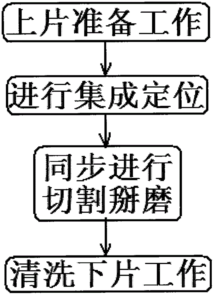
[0061] As shown in the figure, a special-shaped glass remote control cutting, breaking and grinding integrated processing production line is composed of: glass GPS positioning and navigation system 1, special-shaped glass remote cutting machine 2, special-shaped glass remote control edge breaking machine 3, special-shaped glass remote control edge grinding machine 4, Glass remote cleaning machine 5, glass control conveying device 6, sensor conveying device 7, first servo motor 8, first ball screw 9, cutting linkage manipulator 10, edge breaking linkage manipulator 11, edge grinding linkage manipulator 12, cleaning linkage A manipulator 13, a second servo motor 14, and a second ball screw 15 constitute;
[0062] One side of the glass control conveying device 6 is equipped with a sensor conveying device 7, and one side of the sensor conveying device 7 is "keyboard-shaped" and is arranged in sequence with a cutting linkage manipulator 10, an edge breaking linkage manipulator 11, a...
Embodiment 2
[0064] As shown in the figure, a first ball screw 9 is set between the sensor delivery device 7 and the cutting linkage manipulator 10 , and a first servo motor 8 is set at one end of the first ball screw 9 .
Embodiment 3
[0066] As shown in the figure, a second ball screw 15 is arranged between the sensing conveying device 7 and the edging linkage manipulator 12 , and a second servo motor 14 is arranged at one end of the second ball screw 15 .
PUM
 Abstract
Description
Claims
Application Information
 - R&D
- Intellectual Property
- Life Sciences
- Materials
- Tech Scout
- Unparalleled Data Quality
- Higher Quality Content
- 60% Fewer Hallucinations
Browse by: Latest US Patents, China's latest patents, Technical Efficacy Thesaurus, Application Domain, Technology Topic, Popular Technical Reports.
© 2025 PatSnap. All rights reserved.Legal|Privacy policy|Modern Slavery Act Transparency Statement|Sitemap|About US| Contact US: help@patsnap.com


