Resistance furnace

A resistance furnace and resistance wire technology, applied in the direction of electric furnace heating, furnace, furnace type, etc., can solve the problems of increasing the preparation cost of the heating furnace and the difficulty of accurate current control, and achieve the effect of reducing the preparation cost and blocking the loss of energy.

Inactive Publication Date: 2016-05-25
ZHENJIANG XINHANG PRECISION CASTING CO LTD
View PDF8 Cites 0 Cited by
  • Summary
  • Abstract
  • Description
  • Claims
  • Application Information

AI Technical Summary

Problems solved by technology

Its disadvantages are: several current control devices need to be installed, thereby increasing the preparation cost of the heating furnace; the current of each part is not easy to achieve accurate control, so in actual use, the temperature of each section may be the same

Method used


Image

  • Resistance furnace
  • Resistance furnace

Examples


Embodiment Construction

[0011] The following will clearly and completely describe the technical solutions in the embodiments of the present invention with reference to the drawings in the embodiments of the present invention.

[0012] This example figure 1 and figure 2 as shown,

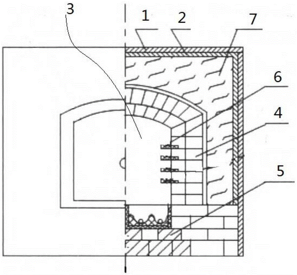
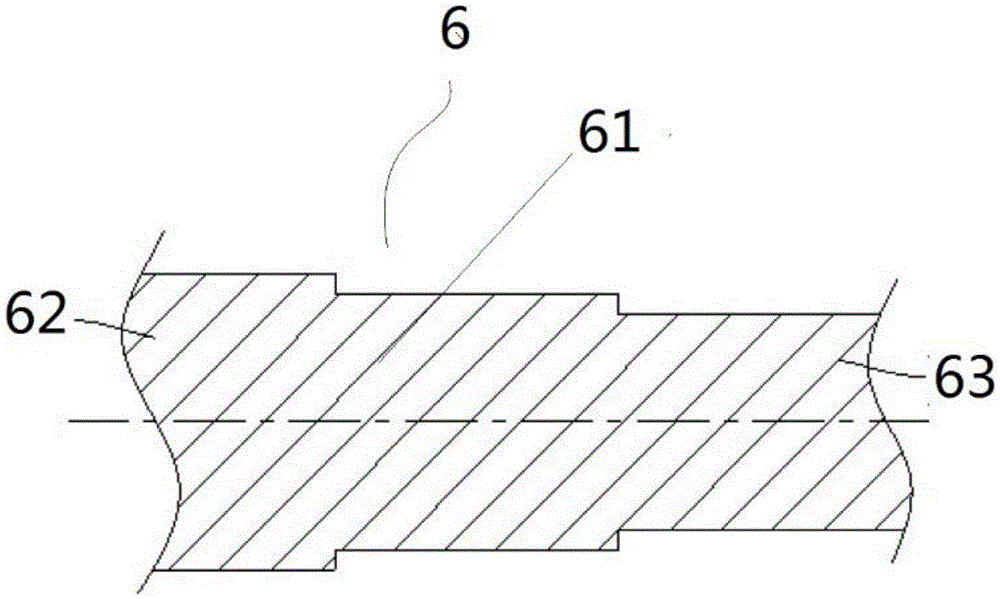
[0013] A resistance furnace, which includes a furnace shell 1, the inner surface of the furnace shell 1 is provided with a heat-insulating fiber felt 2 on the side wall, and the middle part of the furnace shell 1 is provided with a furnace body 3 for storing materials. The furnace body 3 is made of lightweight refractory bricks 4, the bottom of the furnace body 3 is laid with several layers of heavy refractory bricks 5, and the space between the heat-insulating fiber mat 2 and the furnace body 3 is filled with expansion Perlite, said lightweight refractory bricks 4 are provided with resistance wires 6 at intervals, said resistance wires 6 include a resistance wire body 61, said resistance wire body 61 is cylindrical, and...


PUM


Abstract

The invention provides a resistance furnace. A heat-insulating fiber mat that can well hold the temperature in a furnace body is disposed on the sidewall of the inner surface of a furnace shell to obstruct energy dissipation; a resistance wire is directly disposed among light refractory bricks of the furnace body, and in this way, the temperature of the whole furnace body' vertical space may be evenly raised without an excess temperature difference between the bottom and the top; the diameter of the resistance wire decreases gradually from the near end to the distal end; as the diameter of the resistance wire decreases gradually, resistance changes gradually, and the temperature of the furnace body changes gradually. Therefore, multiple current control devices are not necessarily set, and production cost of the heating furnace is effectively reduced; the resistance wire made of aluminum-titanium is more flexible and durable.

Description

technical field [0001] The invention relates to a resistance furnace. Background technique [0002] The resistance furnace is an industrial furnace that uses electric current to heat the electric heating element or heating medium in the furnace, thereby heating the workpiece or material. Resistance furnaces are used in the machinery industry for heating before metal forging, metal heat treatment, brazing, powder metallurgy sintering, glass ceramics firing and annealing, melting of low melting point metals, drying of sand molds and paint films, etc. In the prior art, in the direction of the depth extension of the furnace body, the temperature in the furnace gradually decreases or increases. At present, the commonly used method is to arrange resistance wires with the same diameter in sections along the depth extension direction of the furnace body, but the resistance wires of each section are passed with different working currents. Its disadvantages are: several current cont...

Claims


Application Information

Patent Timeline
Patent Type & Authority Applications(China)
IPC IPC(8): F27B17/00F27D1/10F27D11/02
CPCF27B17/0016F27D1/10F27D11/02
Inventor 洪保平张洁
Owner ZHENJIANG XINHANG PRECISION CASTING CO LTD
Why Eureka
Try Eureka