Integrated fiber F-P chamber pressure sensor

A pressure sensor, F-P technology, applied in the direction of instrumentation, force measurement, and measurement of the change force of the optical properties of the material when it is stressed, can solve non-linearity, reduce the accuracy of F-P pressure sensors, and reduce the accuracy of F-P pressure sensors, etc. problems, to achieve the effect of reducing thermal internal stress, avoiding additional stress, and facilitating pressure adjustment

Pending Publication Date: 2016-05-25
CHENGDU KAITIAN ELECTRONICS
View PDF13 Cites 5 Cited by
  • Summary
  • Abstract
  • Description
  • Claims
  • Application Information

AI Technical Summary

Problems solved by technology

[0008] 3. The glass groove of the pressure-sensitive diaphragm of silicon material is connected by anodic bonding, but the thermal expansion coefficients between the two materials are different, which causes the silicon pressure-sensitive diaphragm to deform due to temperature effects, resulting in There is a nonlinearity between the silicon pressure diaphragm and the pressure, which reduces the accuracy of the F-P pressure sensor;
[0009] 4. At present, the packaging method of the F-P pressure sensor is that the metal casing is directly welded to the sensor head. One of the main disadvantages of this method is that the temperature effect is very obvious. The difference generates additional internal stress, which leads to the change of the cavity length of the F-P cavity, which makes the accuracy of the F-P pressure sensor decrease

Method used


Image

  • Integrated fiber F-P chamber pressure sensor
  • Integrated fiber F-P chamber pressure sensor
  • Integrated fiber F-P chamber pressure sensor

Examples


Embodiment Construction

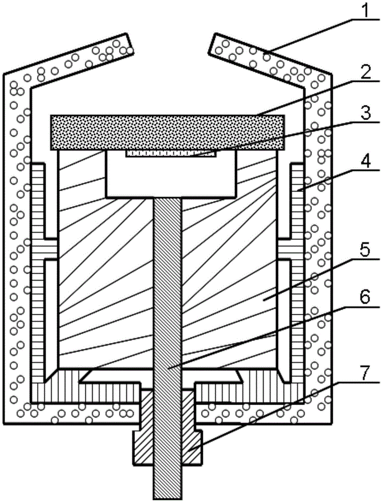
[0023] in as figure 1 In a preferred embodiment shown and described, the integrated optical fiber F-P cavity pressure sensor consists of a packaging shell 1, a pressure diaphragm 2, a composite dielectric film 3, a solid connection member 4, a ferrule 5, an optical fiber 6, and a fixed joint 7. It mainly includes a barrel-shaped packaging casing 1, a pressure diaphragm 2 arranged in the cylinder of the packaging casing 1, a composite dielectric film 3 fixedly connected under the end of the pressure diaphragm 2, and a groove at the end of the ferrule 5 The bottom plane is flush, and the optical fiber 6 protrudes out of the bottom of the packaging shell through the ferrule, and the optical fiber 6 protrudes out of the cylinder of the packaging shell 1 through the fixed joint 7 . The front end of the optical fiber 6 and the composite dielectric film 3 on the pressure diaphragm 2 form a pair of reflective surfaces and form interference fringes, and the external pressure is measure...


PUM

PropertyMeasurementUnit
thicknessaaaaaaaaaa
thicknessaaaaaaaaaa
reflectanceaaaaaaaaaa

Abstract

The invention discloses an integrated fiber F-P chamber pressure sensor. The integrated fiber F-P chamber pressure sensor comprises a barrel-like packaging casing (1), a pressure diaphragm (2) arranged in a packaging casing cylinder, a composite medium film (3) fixedly connected with the bottom end of the pressure diaphragm, and a fiber (6) which is level with a bottom plane of an end portion groove of an insertion core (5) and penetrates through the insertion core to stretch out of the bottom portion of the packaging casing, wherein the composite medium film (3) is just opposite to the top end groove of the insertion core axially, the pressure diaphragm (2) provided with a stress release hole structure is used for packaging the insertion core groove through the bonding technology to form an F-P resonant chamber, the insertion core and the pressure diaphragm are fixedly connected to form an integrated structure, and a circumferential connection fixedly-connected member (4) is assembled on the cylinder of the packaging casing (1) in an integrated mode. According to the integrated fiber F-P chamber pressure sensor, the insertion core provided with the top end groove and the pressure diaphragm are combined with the integrated F-P chamber through the bonding technology, subsequent laser welding and adhesive gluing technologies are saved, the thermal internal stress of a system is further reduced, and performance of the F-P chamber pressure sensor is improved.

Description

technical field [0001] The invention belongs to the technical field of optical fiber sensing, in particular to a high-precision integrated optical fiber F-P cavity pressure sensor. Background technique [0002] Optical fiber sensors use light as the information carrier and optical fiber as the signal transmission medium to sense and measure the measured parameters. It has the advantages of simple structure, small size, high reliability, high sensitivity, short response time, single optical fiber signal transmission, etc. It has attracted widespread attention, and it is also widely used in the health monitoring of petrochemical, aerospace, bridges and other buildings. Its application prospect is one of the current research hotspots. According to different sensor materials, manufacturing methods, etc., optical fiber F-P cavity pressure sensors can be divided into all-fiber structure and MEMS diaphragm type. [0003] The basic structure of the all-fiber structure F-P cavity p...

Claims


Application Information

Patent Timeline
Patent Type & Authority Applications(China)
IPC IPC(8): G01L1/24
CPCG01L1/242
Inventor 孙波熊菠梅运桥
Owner CHENGDU KAITIAN ELECTRONICS
Why Eureka
Try Eureka