Battery cell having a prismatic or cylindrical housing, battery module and motor vehicle
A battery module, battery technology, applied in the directions of large-sized batteries/battery packs, small-sized batteries/battery packs, battery/battery traction, etc., can solve problems such as high cost and complexity, and reduce installation costs and costs. The effect of lowering, reducing parts
Active Publication Date: 2016-05-25
ROBERT BOSCH GMBH +1
View PDF3 Cites 1 Cited by
- Summary
- Abstract
- Description
- Claims
- Application Information
AI Technical Summary
Problems solved by technology
These connections involve complex and costly machining
Method used
View moreImage
Smart ImageViewing Examples

Examples
Embodiment Construction
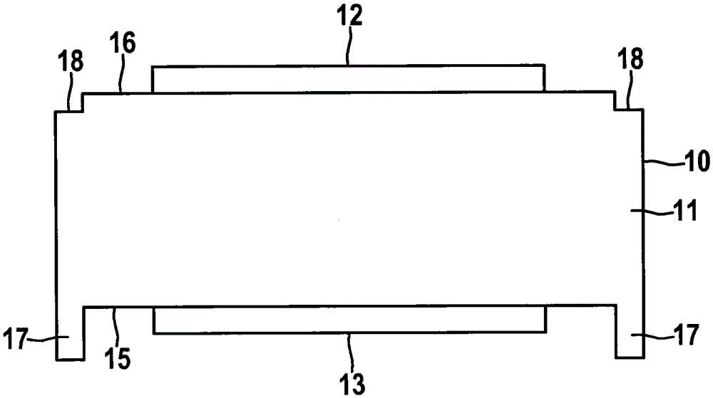
[0038] in figure 2 In the battery cell 10 according to the present invention shown in the figure, one side 15 and the opposite side 16 of the housing 11 are each provided with a connecting terminal 12 and 13 formed by a protrusion.
[0039] The face 15 has a surrounding edge 17 protruding from the plane, while the opposite face 16 has a surrounding edge 18 that is contracted relative to the plane.
Login to View More PUM
 Abstract
The invention relates to a battery cell (10), preferably a lithium ion battery cell, having a prismatic or cylindrical housing (11), in which one side (15) of two opposite sides (15, 16) of the housing (11) is partially or completely at cathode potential, and the second side (16) of the two opposite sides (15, 16) of the housing (11) is partially or completely at anode potential. One of the two sides (15, 16) additionally has a circumferential edge (17) protruding partially or completely from the surface, while the opposite side (16) has a circumferential edge (18) that is partially or completely recessed relative to the surface. Said battery cells (10) can be easily joined together by stacking to form battery modules, making it possible to avoid expensive connecting techniques and production processes. The invention further relates to a battery module and a motor vehicle having an electric drive motor and a battery system.
Description
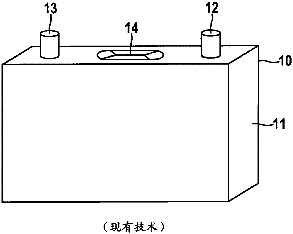
Technical field [0001] The invention relates to a battery cell with a prismatic or cylindrical shell, preferably a lithium ion battery cell, a battery module and a motor vehicle. Background technique [0002] Hybrid electric vehicles (HEV) and electric vehicles (EV) preferably use lithium-ion battery systems as traction batteries due to their relatively high specific energy density, low self-discharge and absence of memory effects. [0003] In order to achieve the power and energy data required for the operation of the drive motor, a large number of single battery cells with a voltage of only about 4V each are connected in series or parallel, so that the total voltage of a battery pack can exceed 450V. [0004] The battery cell is usually a prismatic, cylindrical or so-called pouched secondary battery (also called a coffee pouch cell). [0005] According to the existing technology, the common prismatic battery cell is in figure 1 Shown in. The single cell 10 has a rectangular or pris...
Claims
Login to View More Application Information
Patent Timeline
 Patent Type & Authority Applications(China)
IPC IPC(8): H01M2/02H01M2/10H01M2/20H01M10/052B60L50/64
CPCH01M10/0525H01M10/486H01M2220/20Y02E60/10H01M50/107H01M50/258H01M50/545H01M50/103H01M50/514H01M50/213H01M50/51H01M50/548H01M50/249H01M50/209B60L50/64H01M50/522Y02T10/70Y02P70/50
Inventor F·斯蒂姆M·斯泰尔A·德尔A·博世
Owner ROBERT BOSCH GMBH