Manufacturing method of transparent microstructure

A manufacturing method and microstructure technology, applied in the post-processing of printing, printing, printing devices, etc., can solve the problems of missing patterns, limited types of ink, and slow printing speed, so as to reduce production costs, overcome irregular appearance, and improve The effect of production speed

Active Publication Date: 2016-06-01
SUZHOU INST OF NANO TECH & NANO BIONICS CHINESE ACEDEMY OF SCI
View PDF9 Cites 4 Cited by
  • Summary
  • Abstract
  • Description
  • Claims
  • Application Information

AI Technical Summary

Problems solved by technology

Although the use of these two processes to fabricate transparent microstructure arrays is still in its infancy, the characteristics of the printing process itself determine its limitations: inkjet printing technology requires the viscosity of the ink to be limited to a very low range, and the types of inks available are limited At the same time, the printing speed is relatively slow, and part of the pattern loss due to nozzle clogging is inevitable; and the production speed of screen printing is not fast, and the durability of the screen must be fully considered
However, gravure printing usually uses fast-drying solvents, so the obtained microstructure is difficult to achieve an ideal round crown structure, and the surface will be relatively rough, lacking practical value in optics, and requires structural and surface optimization. To improve the optical performance of the product

Method used


Image

  • Manufacturing method of transparent microstructure
  • Manufacturing method of transparent microstructure

Examples


Embodiment 1

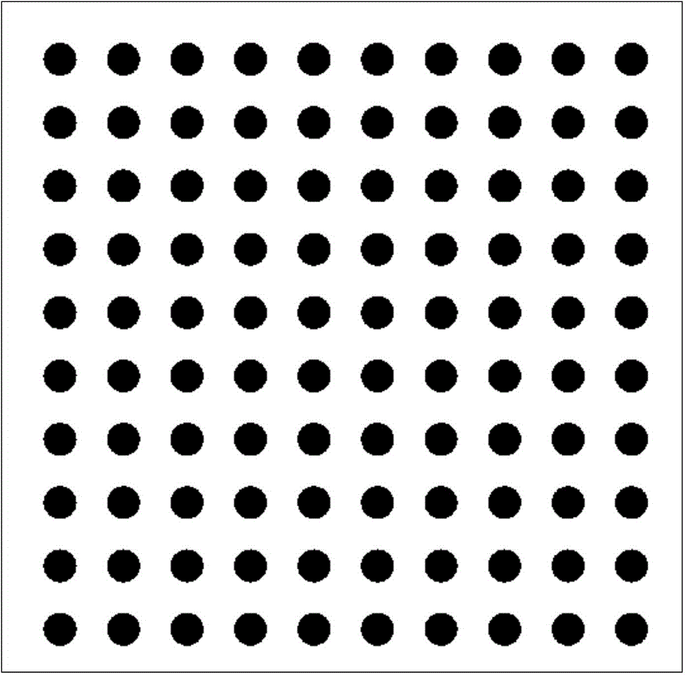
[0038] The commercial transparent polyethylene naphthalate (PEN) that has been cleaned before leaving the factory is cut into a substrate of 120×200mm, and after removing the covering protective film, the main component is directly printed on its surface by gravure printing equipment. Gravure printing ink of acrylic resin, the local cell layout of the flat gravure plate used in the equipment is as follows figure 1 shown. Wherein the diameter of the mesh hole remains unchanged, and the optimal value is taken in the range of 40-60 microns; the depth of the mesh hole is preferably in the range of 8-15 microns, and three different values ​​can be designed according to the requirements of the optical path design, so that The obtained microlenses have different sizes to ensure the ideal optical effect of the entire array. The speed of the whole gravure printing is 5-10 m / min, the pressure between the gravure roller and the transparent PEN is 80-120 Newton, the principle is as follo...

Embodiment 2

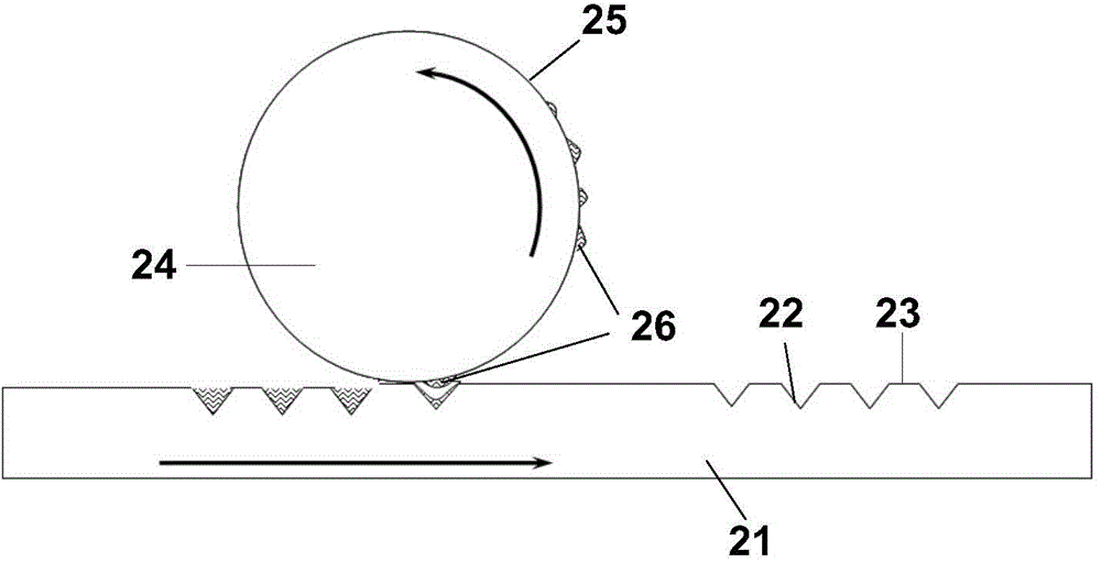
[0041]The commercial high-transmittance glass that has been cleaned before leaving the factory is used as the substrate, and the main components are printed on the glass surface by first printing on the rubber roller and then transferring to the glass by using a 300 mm wide roll-type indirect gravure printing equipment It is a gravure printing ink of transparent polyacrylic resin, and the speed of indirect gravure printing is 3-7 m / min. The diameter of the cells on the gravure roller used is 60-90 microns, and the depth is 10-20 microns. Among them, the diameter of the cell is designed with three different values ​​according to the requirements of the optical path design, and the depth of the cell takes the same optimal value.

[0042] The glass sample obtained by printing stays in a vacuum environment at 180°C and an air pressure of 2-5kPa for 3-5 minutes, so that the transparent polyacrylic resin in the printing ink (melting point temperature is less than 120°C, in a viscous...


PUM

PropertyMeasurementUnit
depthaaaaaaaaaa
diameteraaaaaaaaaa
depthaaaaaaaaaa

Abstract

The invention discloses a manufacturing method of a transparent microstructure. The manufacturing method comprises the following steps: the gravure is performed for ink with a transparent polymer material as an effective component on the surface of a substrate to form an ordered microarray structure; the microarray structure is heated, so that the ink forming the microarray structure is converted to a viscous flow state, and spontaneously shrinks to form a circular crown shape; and the cooling treatment is performed to form the transparent microstructure on the surface of the substrate. The manufacturing method is simple in process, can realize high-speed printing manufacturing of high-quality transparent microstructure, overcomes the defects of thick film, irregular appearance, rough surface and possession of holes in a traditional gravure printing product, prominently improves the product quality and accelerates the production speed, and largely reduces the manufacturing cost.

Description

technical field [0001] The invention relates to a method for preparing a transparent microstructure (such as a microlens array), in particular to a method for manufacturing a transparent microstructure using a gravure printing process. Background technique [0002] The array composed of micron-scale lenses (microlenses) not only has the basic functions of traditional lenses, but also has the characteristics of small unit size and high integration, so that it can complete the functions that traditional optical components cannot complete, and can form many new types of optical components. The system has been widely used in wavefront sensing, light concentration, and light shaping. [0003] With the expansion of the application range of microlens arrays to some low-end products (such as light diffusion plates, light guide plates, etc.), new requirements have been put forward for the production cost control of microlens arrays. Therefore, on the premise that the product performa...

Claims


Application Information

Patent Timeline
Patent Type & Authority Applications(China)
IPC IPC(8): B41M1/10B41M7/00
Inventor 林剑崔铮
Owner SUZHOU INST OF NANO TECH & NANO BIONICS CHINESE ACEDEMY OF SCI
Why Eureka
Try Eureka