
Efficient air cooling structure for converter slag-stopping mechanism

An air-cooled structure, converter slag blocking technology, applied in the direction of manufacturing converters, etc., can solve the problems of easy scalding of construction workers, insufficient air-conditioning pressure, small flow rate and flow rate, etc., to achieve good air-cooling effect, reliable flow and pressure. Variable, reliable cooling effect

Active Publication Date: 2016-06-01
MAANSHAN LIER KAIYUAN NEW MATERIAL
View PDF4 Cites 0 Cited by
  • Summary
  • Abstract
  • Description
  • Claims
  • Application Information

AI Technical Summary

Problems solved by technology

[0003] There are following disadvantages in the above-mentioned two kinds of air cooling methods: (1) figure 1 and figure 2 In the two cooling structures shown, the air-cooling source enters from one end of the spring chamber in the tensioning assembly and flows out from the other end of the spring chamber. In this way, the pressure of the cold air reaching the other end of the spring chamber is not enough and the flow rate becomes smaller, so to The cooling effect is extremely poor when passing through the other end of the spring cavity; (2) online replacement figure 1 For the slag-stopping mechanism of the air-cooled structure shown in the figure: the connection between the air-inlet air-cooling pipe 21 on the converter and the slag-stopping mechanism should be dismantled with a wrench. The temperature at the position of the steel mouth can reach 300°C, so the construction personnel are easily burned, and the construction time is longer; (3) Replacement in offline figure 2 When the refractory brick 23 in the slag retaining mechanism of the shown air-cooled structure, the U-shaped air-cooled pipe 22 must be removed to replace it, and it will be installed after the replacement, which is also laborious and time-consuming; (4) the above two air-cooled structures, in the Under the conditions of converter steelmaking with high slag and high temperature, the exposed air pipes and joints are easily damaged, the air cooling effect is poor, and the actual utilization rate of the air cooling system is not high

Method used


Image

  • Efficient air cooling structure for converter slag-stopping mechanism
  • Efficient air cooling structure for converter slag-stopping mechanism
  • Efficient air cooling structure for converter slag-stopping mechanism

Examples


Embodiment Construction

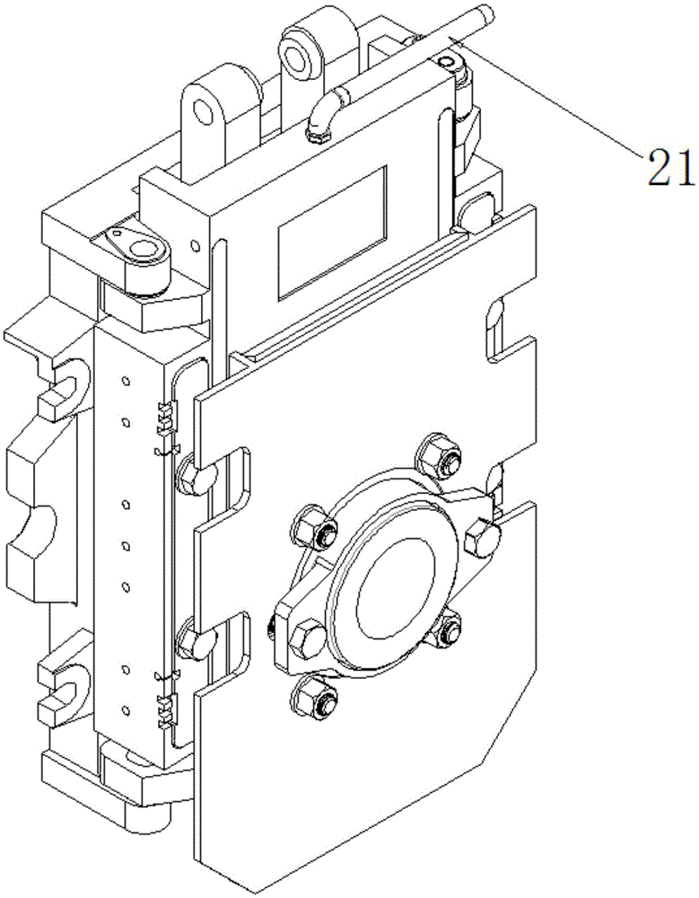
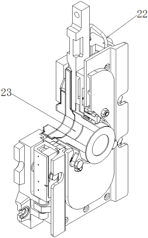
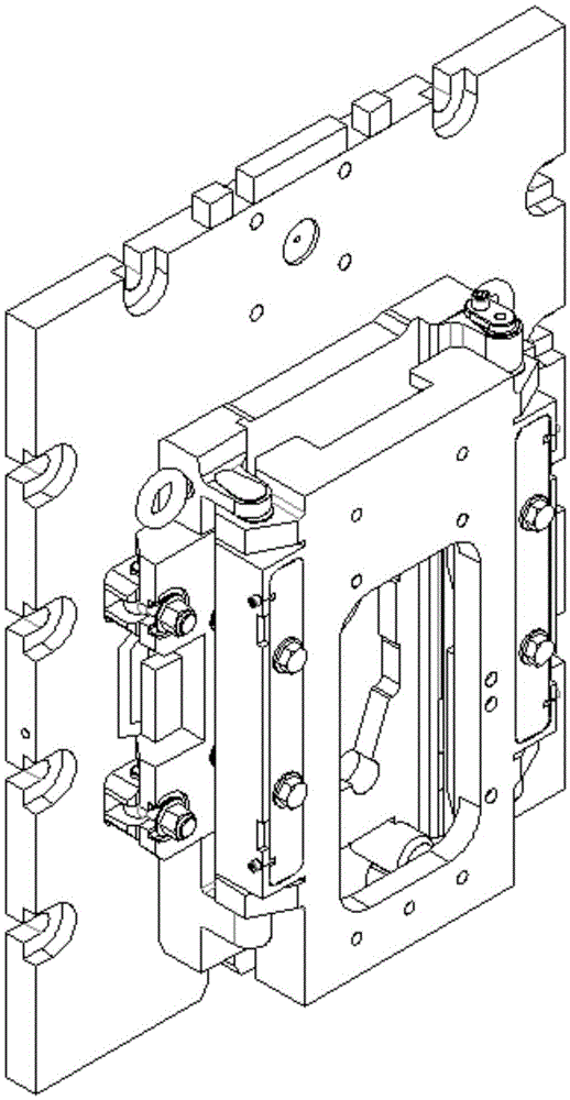
[0018] From image 3 , Figure 4 , Figure 5 , Figure 6 , Figure 7 , Figure 8 , Figure 9 It can be seen that the high-efficiency air-cooled structure of the converter slag blocking mechanism of the present invention includes a connecting assembly body 2, an installation assembly body 5, and a tensioning assembly; the left and right ends of the connecting assembly body 2 are respectively provided with an air inlet 3 symmetrically, and the upper Two air outlets 4 are respectively arranged symmetrically on the left and right, and each air inlet 3 is connected to the upper and lower two air outlets 4 through the air-cooled passage; Four mounting holes, welding nut seats 6 in the mounting holes; the tensioning assembly includes a tensioning assembly body 12, an elastic element 7, a pressing panel 8, and a tensioning bolt 9, and blind grooves are symmetrically arranged on the tensioning assembly body 12 left and right 10. An air outlet 14 is provided at the upper and lower...


PUM


Abstract

The invention discloses an efficient air cooling structure for a converter slag-stopping mechanism. The efficient air cooling structure comprises a connecting assembly body, an installing assembly body and a tensioning assembly. The tensioning assembly comprises a tensioning assembly body, elastic elements, pressing panels and tensioning bolts. Blind grooves are formed in the tensioning assembly body in a bilateral symmetrical mode. Air outlet holes are formed in the upper end and the lower end of each blind groove correspondingly. Each blind groove is provided with one elastic element. The left pressing panel and the right pressing panel are placed on the corresponding elastic elements and are each provided with two through holes. Two through holes are formed in the bottom of each blind groove. The through holes of the pressing panels, the through holes of the bottoms of the blind grooves and nut seat installing holes of the installing assembly body are coaxial. A blind hole is formed in the position, from bottom to top, of the center of each tensioning bolt. Two side holes communicating with each blind hole are formed between the tail end close to each blind hole and the perpendicular direction of each blind hole. According to the efficient air cooling structure for the converter slag-stopping mechanism, the converter slag-stopping mechanism is well cooled, the cooling effect is ensured, and the service life of the converter slag-stopping mechanism is prolonged, so that the cost is reduced.

Description

technical field [0001] The invention relates to steelmaking equipment, in particular to an air-cooled structure on a slag retaining device for converter steelmaking, which can well cool the converter slag retaining mechanism and ensure its service life. Background technique [0002] In converter steelmaking, the slag blocking mechanism is installed on the tapping port, and the mechanism is located directly above the ladle when tapping, especially in the later stage of tapping, the liquid steel is about 1 meter away from the mechanism, and some are even less than 80 cm. However, the body of the mechanism and the key internal elastic components and refractory materials are exposed to high-temperature radiation, and the actual temperature measured by the temperature measuring gun can reach about 500°C. The mechanical performance of each component of the slag blocking mechanism decreases at this high temperature, and the service life is short. In order to cool down the slag blo...

Claims


Application Information

Patent Timeline
IPC IPC(8): C21C5/46
CPCC21C5/4646C21C5/4653
Inventor 梁海波方蓉刘琛赵继增赵峰余西平张家跃马超靳虎
Owner MAANSHAN LIER KAIYUAN NEW MATERIAL
Features
  • Generate Ideas
  • Intellectual Property
  • Life Sciences
  • Materials
  • Tech Scout
  • Unparalleled Data Quality
  • Higher Quality Content
  • 60% Fewer Hallucinations
Learn More