
Differential pressure urea pump for aftertreatment of scr exhaust gas

An exhaust gas post-treatment and differential pressure technology, which is applied in the field of urea pumps, can solve problems such as increased fuel costs, low metering valve power, and low work efficiency, and achieve the effects of avoiding nozzle clogging, stable injection pressure, and improving work efficiency

Active Publication Date: 2018-03-16
山东艾泰克环保科技股份有限公司
View PDF6 Cites 0 Cited by
  • Summary
  • Abstract
  • Description
  • Claims
  • Application Information

AI Technical Summary

Problems solved by technology

[0002] In the prior art, there is a disadvantage in the method for exhaust gas treatment of internal combustion engines, that is, the purification treatment of PM and nitrogen oxides cannot be realized at the same time, and the two conflict with each other
For example, using Exhaust Gas Recirculation (EGR, Exhaust GasRecycle) technology to purify the exhaust gas of internal combustion engines can greatly reduce the content of nitrogen oxides in the exhaust gas, but the content of PM in the exhaust gas increases instead, and the fuel cost increases; High-pressure injection technology purifies and treats the exhaust gas of internal combustion engines, which is beneficial to reduce the content of PM in the exhaust gas, but often increases the content of nitrogen oxides in the exhaust gas
In order to protect the environment, countries around the world have successively issued relevant regulations to control vehicle exhaust emissions. The increasingly stringent emission regulations make it difficult for pure in-machine purification technology to meet the requirements of the regulations, and must rely on off-machine after-treatment technology to assist.
[0003] In terms of off-machine technical treatment, currently major domestic diesel engine companies and OEMs mainly use selective catalytic reduction system technology to control the nitrogen oxide emissions of diesel engines, and the selective catalytic reduction system needs to use a urea pump to extract urea from the urea tank solution, and spray it into the exhaust pipe with a certain precision. When the injection of ordinary differential pressure urea pump is slightly blocked, the power of the metering valve is small, and it cannot be forced to discharge the liquid, causing the reductant to crystallize in the pump and block the pump.
At present, similar pumps usually use air-controlled diaphragm valves as return valves. This type of valve has the problems of easy leakage, difficult processing of the cavity, and inflexible control.
Ordinary external mixing urea pumps have no forced purging function, and there is a risk of crystallization at the outlet of the nozzle, and after the ordinary internal mixing nozzle is blocked, it is easy to cause urea to flow to the air channel to crystallize and block, because the air channel of the ordinary differential pressure pump uses ordinary mechanical The one-way valve, the air flow channel cannot be closed effectively in time, causing urea to enter the air flow channel and form urea crystals to block the flow channel. The module is heated, the work efficiency is low, and the heating procedure is complicated

Method used


Image

  • Differential pressure urea pump for aftertreatment of scr exhaust gas

Examples


Embodiment 1

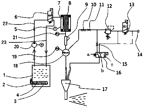
[0013] Embodiment 1, with reference to figure 1 . A differential pressure urea pump for aftertreatment of SCR exhaust gas, comprising a urea tank 1, a pre-mixer 18 and an air inlet 14, characterized in that: the urea tank 1 is provided with a heating unit 2, and the heating unit 2 The reductant in the urea tank 1 is heated, and the urea tank 1 is connected with the liquid return solenoid valve 6 through the liquid suction pipeline 22 and the liquid return pipeline 23, and the liquid return solenoid valve 6 is connected with a voltage stabilizer 8, and the stabilizer A filter element 7 is provided outside the pressurizer 8, and the pressurizer 8 is connected to a metering valve 9, and a pressure sensor 21 is arranged between the metering valve 9 and the pressurizer 8, and the metering valve 9 is connected to the 18 pre-mixer. The pre-mixer 18 is provided with a pressure sensor 19, and the pre-mixer 18 is connected to an electromagnetically driven one-way valve 10, and the elect...

Embodiment 2

[0014] Example 2, in the differential pressure urea pump for SCR exhaust gas post-treatment described in Example 1: the heating unit includes a water inlet pipe 3 and a water outlet pipe 4, and the water inlet pipe 3 and the water outlet pipe 4 The bottom communicates through a heat exchanger.

Embodiment 3

[0015] Embodiment 3, in the differential pressure urea pump for SCR exhaust gas post-treatment described in Embodiment 1 or 2: a flow restrictor 11 is provided between the electromagnetically driven one-way valve 10 and the air pressure regulator 12 .


PUM


Abstract

A differential pressure type urea pump for SCR exhaust gas after-treatment comprises a urea box, a premixer and an air inlet and is characterized in that a heating unit is arranged in the urea box and heats reducing agents in the urea box, the urea box is connected to a liquid return solenoid valve through a liquid suction pipeline and a liquid return pipeline, the liquid return solenoid valve is connected to a pressure stabilizer, a filter core is arranged outside the pressure stabilizer, the pressure stabilizer is connected to a metering valve, the metering valve is connected to the premixer, the premixer is connected to a solenoid drive check valve, the solenoid drive check valve is connected to an air pressure adjuster, the rear part of the air pressure adjuster is connected to an air valve, the air valve is connected to a second hydraulic port of a strong-blowing solenoid valve through a pipeline, the rear part of the air valve is connected to the air inlet, and the strong-blowing solenoid valve and the premixer are connected to a nozzle simultaneously.

Description

technical field [0001] The invention relates to the technical field of urea pumps, in particular to a differential pressure urea pump used for aftertreatment of SCR tail gas. Background technique [0002] In the prior art, there is a shortcoming in the method for exhaust gas treatment of internal combustion engines, that is, the purification treatment of PM and nitrogen oxides cannot be realized at the same time, and the two conflict with each other. For example, using Exhaust Gas Recirculation (EGR, Exhaust GasRecycle) technology to purify the exhaust gas of internal combustion engines can greatly reduce the content of nitrogen oxides in the exhaust gas, but the content of PM in the exhaust gas increases instead, and the fuel cost increases; High-pressure injection technology purifies and treats the exhaust gas of internal combustion engines, which is beneficial to reduce the content of PM in the exhaust gas, but often increases the content of nitrogen oxides in the exhaust...

Claims


Application Information

Patent Timeline
Patent Type & Authority Patents(China)
IPC IPC(8): F01N3/20F01N3/28
CPCF01N3/2006F01N3/208F01N3/28Y02T10/12
Inventor 王用林檀荣科王小波李英文孙克亮
Owner 山东艾泰克环保科技股份有限公司
Learn More