LTCCC laminated wideband microstrip staggered triangle array antenna

An array antenna and triangular technology, which is applied to antennas, antenna arrays, and devices that enable antennas to work in different bands at the same time, can solve the unfavorable development needs of conformal and miniaturized microstrip patch antennas and carriers, and can not take into account the antenna Broadband and miniaturization, narrow frequency band of microstrip patch antenna and other issues, to achieve the effect of reducing size, realizing miniaturization and expanding bandwidth

Inactive Publication Date: 2016-06-01
UNIV OF ELECTRONICS SCI & TECH OF CHINA
View PDF4 Cites 7 Cited by
  • Summary
  • Abstract
  • Description
  • Claims
  • Application Information

AI Technical Summary

Problems solved by technology

In the current navigation and communication system, the microstrip antenna accounts for almost half of it; however, the frequency band of the microstrip patch antenna is very narrow. The current common ways to solve this problem include using thick substrates or stepped substrates, reducing the dielectric constant of the substrate, increasing the Large substrate loss tangent, multi-layer structure, a

Method used


Image

  • LTCCC laminated wideband microstrip staggered triangle array antenna
  • LTCCC laminated wideband microstrip staggered triangle array antenna
  • LTCCC laminated wideband microstrip staggered triangle array antenna

Examples


Embodiment Construction

[0022] The present invention will be described in further detail below in conjunction with the accompanying drawings and specific embodiments, but the embodiments of the present invention are not limited thereto.

[0023] Such as Figure 8 As shown, the center frequency point of the LTCC laminated broadband microstrip interleaved triangular array antenna provided in this embodiment is 9.98 GHz, which is a common microstrip patch antenna for transmitting and receiving. This embodiment can realize a microstrip patch with an impedance bandwidth of 1.36 GHz antenna.

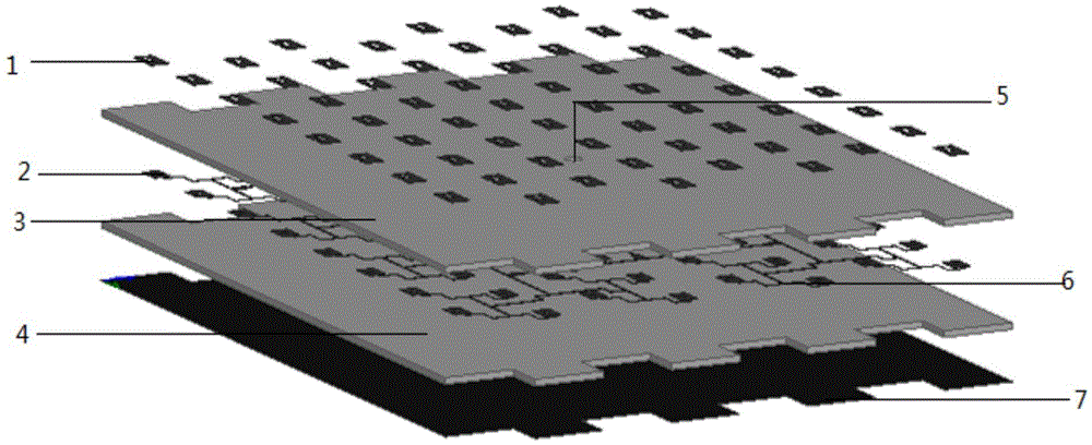
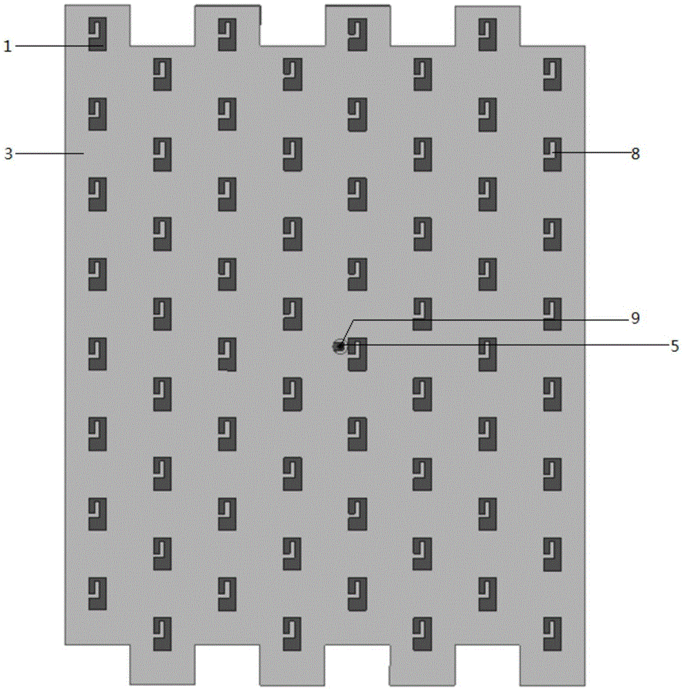
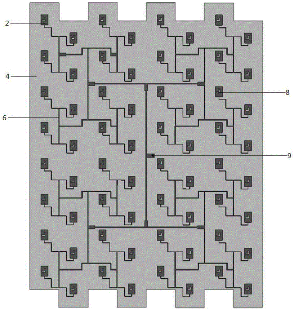
[0024] In this embodiment, a LTCC laminated broadband microstrip interleaved triangular array antenna has a structure such as Figure 1 to Figure 7 shown, including:

[0025] Lower dielectric substrate (4): the substrate is made of 10 sheets of LTCC cast film with a thickness of 0.1 mm and a dielectric constant of 5.9; the lower surface of the substrate is printed with a grounding metal layer (7) with silver paste;...


PUM


Abstract

The invention belongs to the technical field of antennas, and provides an LTCC laminated wideband microstrip staggered triangle array antenna. The LTCC laminated wideband microstrip staggered triangle array antenna is used for overcoming the disadvantages of an existing microstrip patch antenna in the aspects of giving consideration to high gain, wide frequency band and miniaturization. The antenna comprises an upper radiation metal patch antenna array, a lower radiation metal patch antenna array, an upper dielectric substrate, a lower dielectric substrate, a welding hole, a feed network, a grounding metal layer and a coaxial connector probe, and is characterized in that the upper dielectric substrate, the lower dielectric substrate and the grounding metal layer are respectively in the shapes of rectangles with teeth; the upper metal patch antenna array and the lower metal patch antenna array are respectively composed of upper unit metal patches and lower unit metal patches in the arrangement of staggered triangles; and the upper unit metal patches and the lower unit metal patches are respectively in the shapes of rectangles provided with semi-U-shaped grooves. The LTCC laminated wideband microstrip staggered triangle array antenna provided by the invention can well give the consideration to the performance requirements of the microstrip patch antenna such as high gain, wide frequency band and miniaturization, and is relatively simple in structure.

Description

technical field [0001] The invention belongs to the technical field of antennas, in particular to an LTCC stacked broadband microstrip interleaved triangular array antenna. Background technique [0002] Since the microstrip antenna theory has been widely studied in the 1970s and has achieved great development, it has become more and more popular because of its advantages such as light weight, low profile, small size, easy to conform to the carrier, and simple structure. , have been used more and more in the fields of airborne, spaceborne, missile-borne antennas, medical microwaves and civil communications. In the current navigation and communication system, the microstrip antenna accounts for almost half of it; however, the frequency band of the microstrip patch antenna is very narrow. The current common ways to solve this problem include using thick substrates or stepped substrates, reducing the dielectric constant of the substrate, increasing the Large substrate loss tang...

Claims


Application Information

Patent Timeline
IPC IPC(8): H01Q1/38H01Q1/36H01Q5/50H01Q21/00
CPCH01Q1/38H01Q1/36H01Q21/00
Inventor 张怀武李丽君李贵栋
Owner UNIV OF ELECTRONICS SCI & TECH OF CHINA
Why Eureka
Try Eureka