Gas engine driven steam compressing and absorbing combined type heat pump hot water unit running method

A vapor compression, heat pump hot water technology, applied in heat pumps, refrigerators, refrigeration components, etc., can solve problems such as the quality of waste heat is not further improved, the efficiency of energy utilization is not high, and the advantages of gas engine heat pumps cannot be fully utilized. Improve the efficiency and efficiency of primary energy utilization, improve primary energy utilization, and improve the effect of primary energy utilization

Active Publication Date: 2016-06-15
蓝焰高科(天津)燃气技术有限公司
View PDF5 Cites 12 Cited by
  • Summary
  • Abstract
  • Description
  • Claims
  • Application Information

AI Technical Summary

Problems solved by technology

However, the waste heat of the gas engine is only used for auxiliary heating and domestic hot water preparation, and the quality of waste heat has not been further improved
Moreover, various buildings such as office buildings and office buildings do not require a large amount of domestic hot water, so the applicability is limited, and the advantages of gas engine heat pumps cannot be fully utilized.
[0003] At present, there is a gas engine-driven vapor compression heat pump system structure, which only uses the waste heat of the engine to produce hot water, and the energy utilization rate and The efficiency is not high, and the quality of waste heat has not improved

Method used


Image

  • Gas engine driven steam compressing and absorbing combined type heat pump hot water unit running method

Examples


Embodiment 1

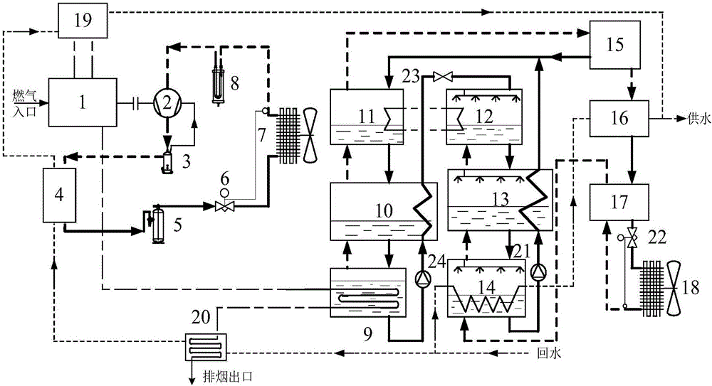
[0029] The gas engine 1 drives the compressor 2 to do work, and compresses the refrigerant in the compression heat pump system into a high-temperature and high-pressure gaseous state. The gaseous refrigerant first passes through the oil separator 3, and then enters the first condenser 4 to be heated by the first user return water. The heat is transferred to the user's return water by exchange, and the refrigerant condenses into a relatively low-temperature high-pressure liquid state, enters the liquid receiver 5, and then expands through the expansion valve 6 to become a low-temperature and low-pressure liquid state and then enters the first evaporator. The first evaporator 7 absorbs the heat of the external environment and evaporates into a gaseous state. The gaseous refrigerant enters the compressor 2 through the gas-liquid separator 8 and is compressed into a high-temperature and high-pressure gaseous state, thus forming a compressed refrigerant cycle. ;

[0030] The waste ...

Embodiment 2

[0035] The gas engine 1 drives the compressor 2 to do work, and compresses the refrigerant in the compression heat pump system into a high-temperature and high-pressure gaseous state. The gaseous refrigerant first passes through the oil separator 3, and then enters the first condenser 4 to be heated by the first user return water. The heat is transferred to the user's return water by exchange, and the refrigerant condenses into a relatively low-temperature high-pressure liquid state, enters the liquid receiver 5, and then expands through the expansion valve 6 to become a low-temperature and low-pressure liquid state and then enters the first evaporator. The first evaporator 7 absorbs the heat of the external environment and evaporates into a gaseous state. The gaseous refrigerant enters the compressor 2 through the gas-liquid separator 8 and is compressed into a high-temperature and high-pressure gaseous state, thus forming a compressed refrigerant cycle. ;

[0036] The waste ...

Embodiment 3

[0041] The gas engine 1 drives the compressor 2 to do work, and compresses the refrigerant in the compression heat pump system into a high-temperature and high-pressure gaseous state. The gaseous refrigerant first passes through the oil separator 3, and then enters the first condenser 4 to be heated by the first user return water. The heat is transferred to the user's return water by exchange, and the refrigerant condenses into a relatively low-temperature high-pressure liquid state, enters the liquid receiver 5, and then expands through the expansion valve 6 to become a low-temperature and low-pressure liquid state and then enters the first evaporator. The first evaporator 7 absorbs the heat of the external environment and evaporates into a gaseous state. The gaseous refrigerant enters the compressor 2 through the gas-liquid separator 8 and is compressed into a high-temperature and high-pressure gaseous state, thus forming a compressed refrigerant cycle. ;

[0042]The waste h...


PUM


Abstract

The invention discloses a gas engine driven steam compressing and absorbing combined type heat pump hot water unit running method. The method includes the following steps that a gas engine drives a compressor to act. A refrigerant is compressed into high-temperature and high-pressure gas, becomes liquid after heat exchange and enters the compressor after absorbing heat and being evaporated into gas, and compression type refrigerant cycling is formed. The method further includes solution cycling and refrigerant cycling, hot user return water is divided into two ways to be heated; the first way of return water is subjected to heat exchange with exhaust fume of the gas engine in an exhaust fume heat exchanger and then enters a first condenser and a cylinder sleeve heat exchanger in sequence to be subjected to heat exchange, and therefore the temperature of the return water can be increased; and the second way of return water absorbs absorbing heat generated in an external cooling absorber, then enters a second condenser, is subjected to heat exchange with ammonia steam in the second condenser and is provided for a user to use after being heated. By means of the method, the primary energy ratio can be increased.

Description

technical field [0001] The invention relates to an operation method of a composite heat pump water heater, in particular to a gas engine driven steam compression and absorption composite heat pump water heater operation method. Background technique [0002] In the gas engine-driven compression heat pump system, based on the physical properties of the refrigerant and the second law of thermodynamics, the gas engine drives the compressor to do work, and cooperates with the condenser, expansion valve, and evaporator to change the state of the refrigerant. To achieve the purpose of cooling and heating. At the same time, the gas engine produces a large amount of heat output, including two parts: the waste heat of the circulating water in the engine and the waste heat of the flue gas. There are many forms of waste heat utilization, such as auxiliary evaporation, defrosting, and domestic hot water. However, the waste heat of the gas engine is only used for auxiliary heating and d...

Claims


Application Information

Patent Timeline
Patent Type & Authority Applications(China)
IPC IPC(8): F24H4/02F25B30/04F24H9/00
CPCF24H4/02F24H9/0005F25B30/04
Inventor 刘凤国加磊磊董付江韩冰冰赵雁刘亚军
Owner 蓝焰高科(天津)燃气技术有限公司
Why Eureka
Try Eureka