
Waste heat recovery system based on data center and control method for waste heat recovery system

A waste heat recovery system and waste heat technology, applied in the field of waste heat recovery, can solve the problems of aggravating the greenhouse effect, environmental pollution, energy waste, etc., and achieve the effects of avoiding environmental pollution, improving environmental protection performance, and reducing energy waste

Pending Publication Date: 2018-08-31
ZHONGSHOUNENG ENERGY INVESTMENT BEIJING CO LTD
View PDF3 Cites 10 Cited by
  • Summary
  • Abstract
  • Description
  • Claims
  • Application Information

AI Technical Summary

Problems solved by technology

And because the data center computer room has various types of servers, data storage devices, and network equipment, these electrical equipment generate a large amount of heat and the heat is relatively concentrated, resulting in the data center computer room emitting a large amount of heat all year round. The heat is discharged into the atmosphere, which not only causes A large amount of energy is wasted, and it causes environmental pollution and aggravates the greenhouse effect

Method used


Image

  • Waste heat recovery system based on data center and control method for waste heat recovery system
  • Waste heat recovery system based on data center and control method for waste heat recovery system
  • Waste heat recovery system based on data center and control method for waste heat recovery system

Examples


Embodiment 1

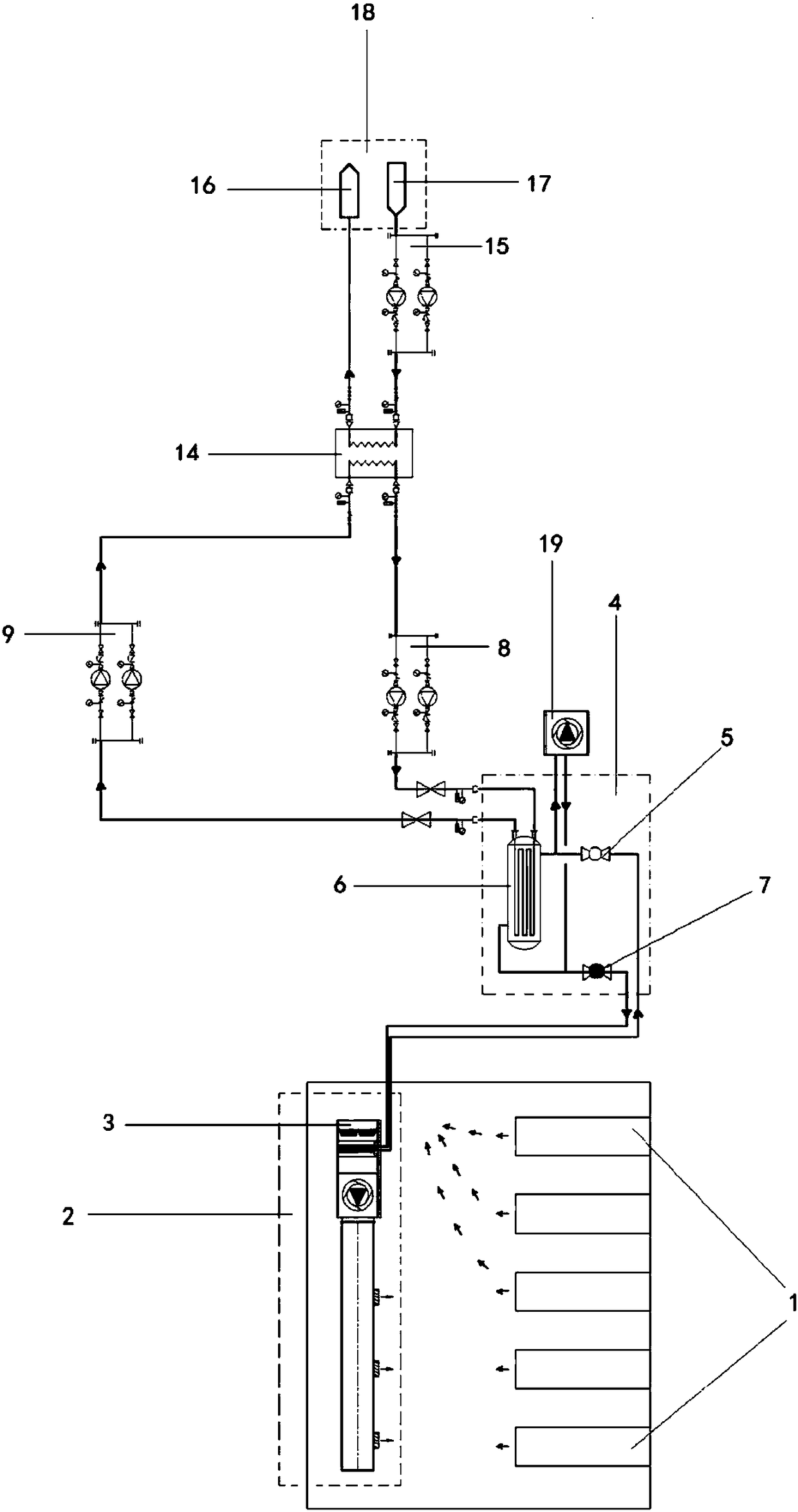
[0085] Please refer to figure 1 and Figure 8 .

[0086] Please refer to figure 1 . In a specific implementation, the waste heat recovery system provided by the present invention is used to recover and utilize the waste heat generated by the data center, and the waste heat recovery system includes a waste heat collection unit 2 , a heat pump unit 4 , a waste heat delivery unit and a user terminal 18 .

[0087] Wherein, the waste heat collection unit 2 includes an evaporator 3, which is used to collect heat generated in the computer room of the data center, and absorb heat through the evaporator 3 to generate low-temperature and low-pressure gas; the heat pump unit 4 includes compressors connected in sequence 5. A condenser 6 and a throttling device 7, the compressor 5 communicates with the heat output end of the evaporator 3 through a Freon pipeline, and the condenser 6 forms a medium circulation circuit with the waste heat delivery unit;

[0088] The heat pump unit 4 comm...

Embodiment 2

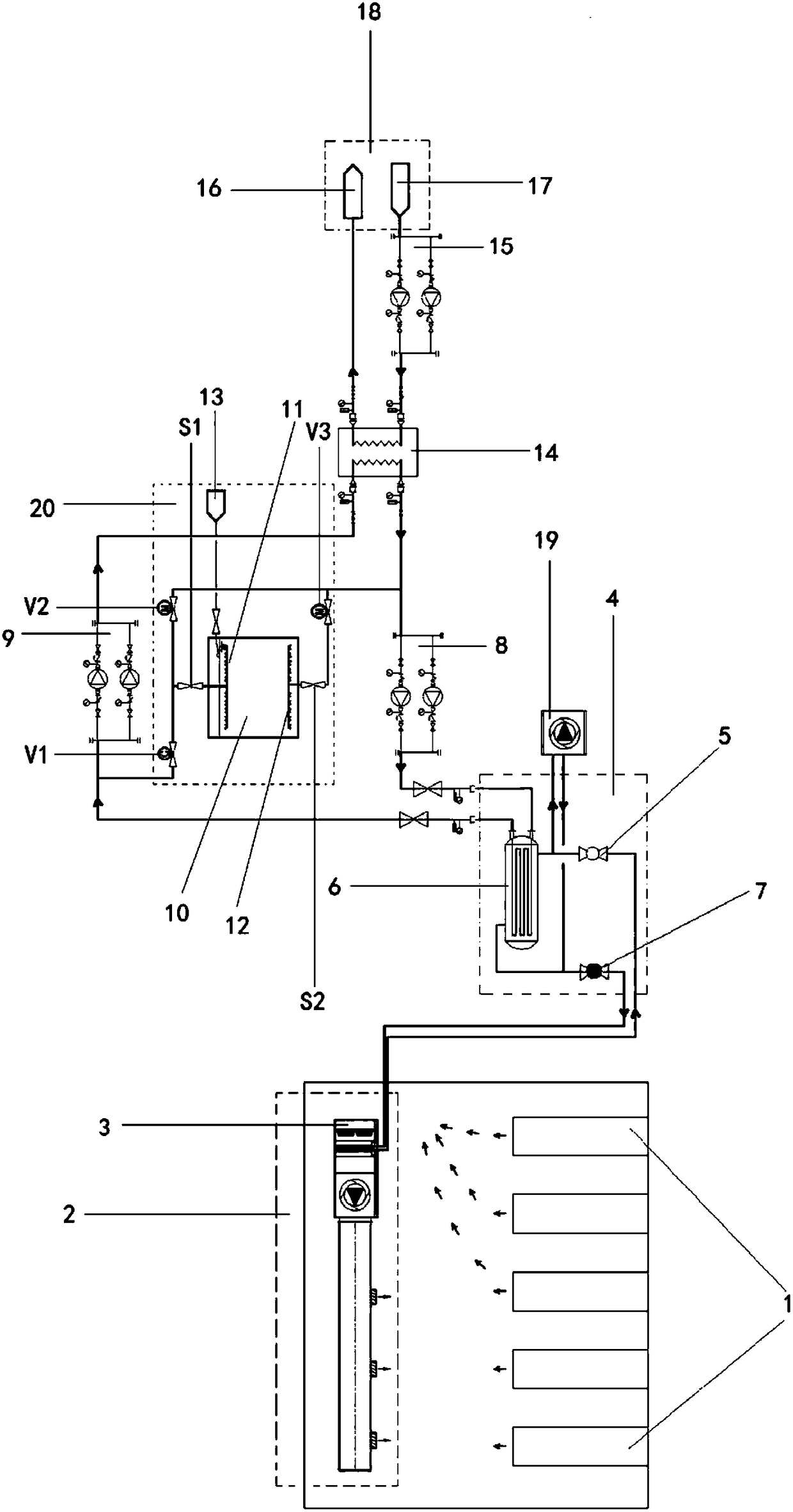
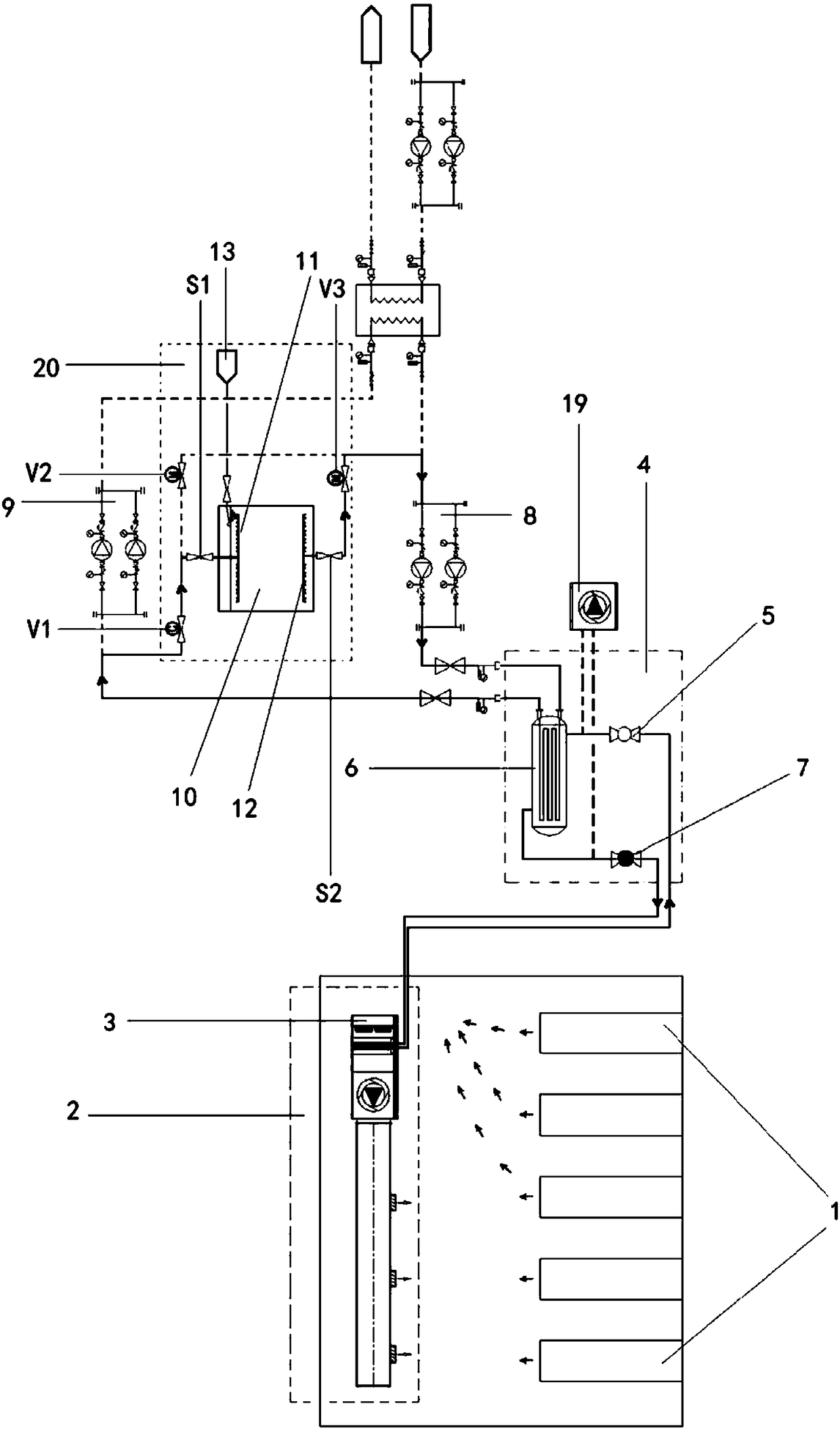
[0131] Please refer to figure 2 , image 3 , Figure 4 , Figure 5 , Figure 6 , Figure 7 and Figure 9 .

[0132] Please refer to figure 2 . In a specific implementation, the waste heat recovery system provided by the present invention is used to recover and utilize the waste heat generated by the data center, and the waste heat recovery system includes a waste heat collection unit 2 , a heat pump unit 4 , a waste heat delivery unit and a user terminal 18 .

[0133] Furthermore, when there is too much waste heat generated in certain periods of time and the user terminal 18 cannot fully utilize it, this part of waste heat can be stored first, and then released for use when the waste heat is insufficient, so as to improve the utilization rate of waste heat.

[0134] In order to achieve the above purpose, a heat storage unit 20 can be installed on the circuit of the waste heat delivery unit, and the heat storage unit 20 includes a heat storage device 10, a pipeline eq...


PUM


Abstract

The invention discloses a waste heat recovery system based on a data center and a control method for the waste heat recovery system. The waste heat recovery system comprises a waste heat collecting unit, a heat pump unit, a heat storage unit, a waste heat conveying unit and a user end. The waste heat recovery system has the advantages that the waste heat collecting unit collects heat generated ina machine room of the data center, and the heat is transmitted to the user end through the waste heat conveying unit after being compressed and condensed by the heat pump unit; the waste heat recoverysystem further stores a part of waste heat in advance through the heat storage unit, when the waste heat is insufficient, the waste heat is released and used, and therefore the waste heat utilizationrate is increased; the purposes that the indoor waste heat is extracted and utilized, circulating water of a heat supply network is heated, and heat supply is realized can be achieved by the waste heat recovery system; and the heat generated by the machine room of the data center can be recycled and reused by the waste heat recovery system, so that energy waste and environmental pollution causedby emission of the waste heat of the machine room can be avoided.

Description

technical field [0001] The invention relates to the technical field of waste heat recovery, in particular to a data center-based waste heat recovery system. The invention also relates to a control method for the waste heat recovery system. Background technique [0002] The data center computer room is a place that provides an operating environment for electronic information equipment, which usually includes: power supply and distribution systems, integrated wiring systems, air-conditioning and fresh air systems, security systems, environmental power monitoring systems, fire protection systems, KVM systems and other network equipment. And because the data center computer room has various types of servers, data storage devices, and network equipment, these electrical equipment generate a large amount of heat and the heat is relatively concentrated, resulting in the data center computer room emitting a large amount of heat all year round. The heat is discharged into the atmosph...

Claims


Application Information

Patent Timeline
Patent Type & Authority Applications(China)
IPC IPC(8): F24F12/00F24F11/84F24F11/64F24F140/20
CPCF24F11/64F24F11/84F24F12/00F24F2140/20Y02B30/56
Inventor 郭庆沅倪文岗
Owner ZHONGSHOUNENG ENERGY INVESTMENT BEIJING CO LTD
Learn More