Full visual field low frequency heterodyne point diffraction interferometer

A full field of view and interferometer technology, applied in the field of optical imaging, can solve problems such as difficult to accurately drive large-mass objects, complex manufacturing process of diffractive small holes, changing wavefront phase distribution, etc., to achieve difficulty in development and cost reduction, Increased measurement numerical aperture range, easy to obtain results

Active Publication Date: 2016-06-15
ACAD OF OPTO ELECTRONICS CHINESE ACAD OF SCI
View PDF6 Cites 6 Cited by
  • Summary
  • Abstract
  • Description
  • Claims
  • Application Information

AI Technical Summary

Problems solved by technology

However, the mechanical phase shift driven by piezoelectricity is not suitable for large-diameter target mirrors, and it is difficult for piezoelectric ceramics to accurately drive large objects; in addition, if the converged light spot of the measured mirror is la

Method used


Image

  • Full visual field low frequency heterodyne point diffraction interferometer
  • Full visual field low frequency heterodyne point diffraction interferometer
  • Full visual field low frequency heterodyne point diffraction interferometer

Examples


Embodiment Construction

[0044] The technical solutions in the embodiments of the present invention will be clearly and completely described below in conjunction with the accompanying drawings in the embodiments of the present invention. Obviously, the described embodiments are only some of the embodiments of the present invention, not all of them. Based on the embodiments of the present invention, all other embodiments obtained by persons of ordinary skill in the art without making creative efforts belong to the protection scope of the present invention.

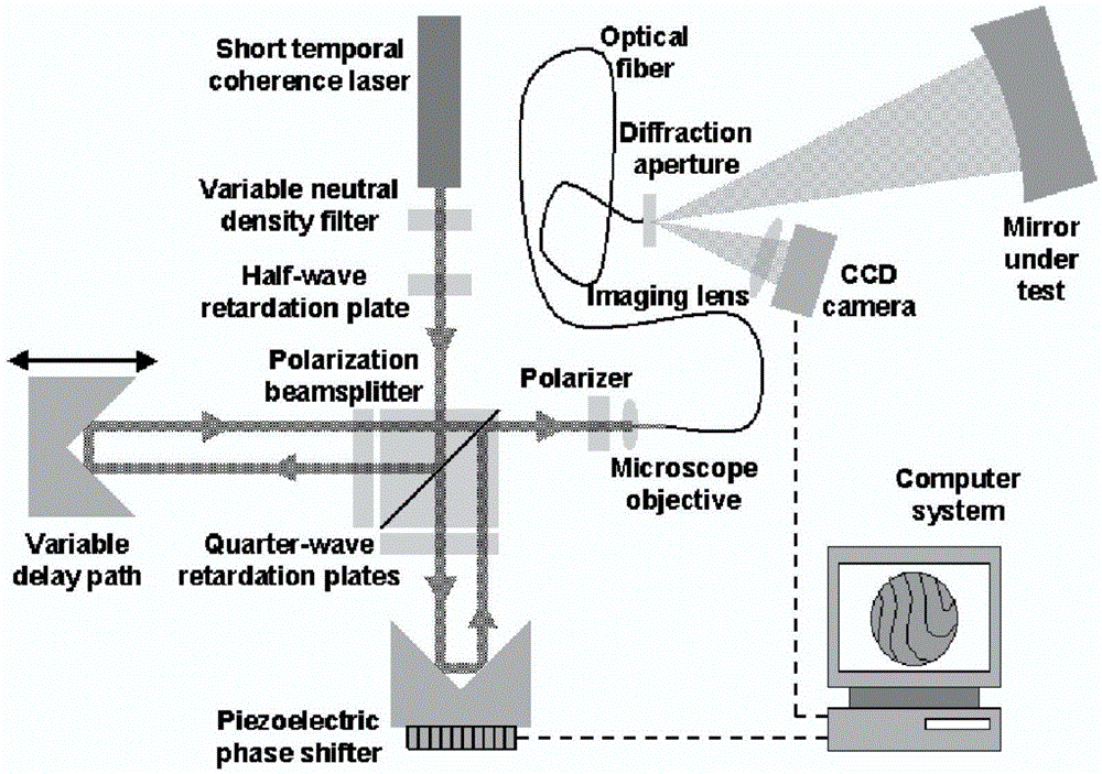
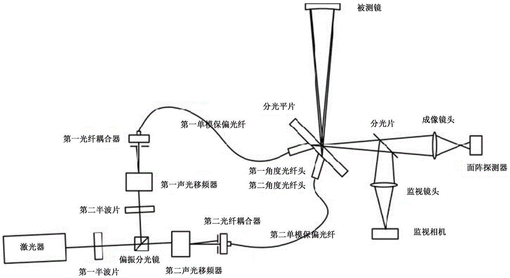
[0045] image 3 A schematic structural diagram of a full-field low-frequency heterodyne diffraction interferometer provided by an embodiment of the present invention. Such as image 3 As shown, it mainly includes:

[0046] A full-field low-frequency heterodyne diffraction interferometer is characterized in that it includes: lasers, first and second half-wave plates, polarization beam splitters, first and second acousto-optic frequency shifters, f...


PUM

PropertyMeasurementUnit
Thicknessaaaaaaaaaa

Abstract

The invention discloses a full visual field low frequency heterodyne point diffraction interferometer. An acousto-optic frequency shifter is adopted to shift phase by heterodyne interference so that moving members of the interferometer are avoided, and measurement accuracy is further increased. The interferometer has good anti-interference performance, reduced development difficulty and cost, and compared with mechanical drive, the interferometer has more obvious advantages. Two optical fibers are used to respectively generate measuring light and reference light instead of part of emitting light; the interferometer combines the advantages that optical fiber point diffraction light is easy to access and flexible to adjust; compared with typical optical fiber point diffraction interferometer system, the measurement value aperture diameter range is increased. Besides, beam combination of point diffraction measurement light and reference light is realized by gluing angle ground fiber tips with light splitting plain films, wherein the beam combination is realized through outer sides of the semi-transparent and semi-reflection plain films, interference of diffraction opening edges on wave front of convergence light spots is avoided. The interferometer is easy to operate and has low cost.

Description

technical field [0001] The invention relates to the technical field of optical imaging, in particular to a full-field low-frequency heterodyne diffraction interferometer. Background technique [0002] The high-end optical equipment represented by the projection exposure system of the deep ultraviolet lithography machine poses great challenges to the processing of optical components and the integration of optical systems. Interferometer is an indispensable core detection equipment for high-precision optical component processing and optical system integration, and the detection accuracy requirements are constantly improving. [0003] The optical surface shape detection methods used in traditional optical processing include Hartmann sensor method, knife edge method and contour method. These methods have different disadvantages such as non-digital subjective interpretation or contact damage to the test piece, and it is difficult to achieve high measurement accuracy. They are si...

Claims


Application Information

Patent Timeline
IPC IPC(8): G01B9/02G01B11/24
CPCG01B9/0201G01B9/02015G01B9/02076G01B9/02096G01B11/2441
Inventor 张文喜李杨相里斌伍洲孔新新吕笑宇刘志刚郭晓丽
Owner ACAD OF OPTO ELECTRONICS CHINESE ACAD OF SCI
Why Eureka
Try Eureka